Creating an Engineering Connection with Smart Positioning | ||||||
|
| |||||
Click Engineering Connection
 .
.
The Engineering Connection Definition dialog box and the Engineering Connection Assistant toolbar appear.
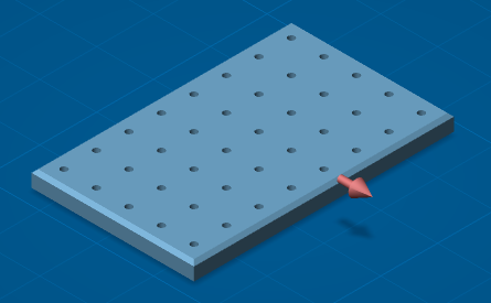
The assembly looks like this:
Select the Smart Positioning
 option.
Select the first component.
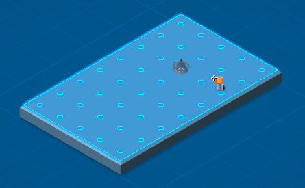
A tooltip is displayed in the right-top corner of the Authoring window, indicating the number of solutions found according to existing publications in the two components:
- When there is no solution or while you have not move the first component over the second component:
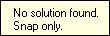
Important: - When no solution exists, the snap capabilities is initialized. See Snapping Components in an Engineering Connection
- There is no solution for repositionable component.
.
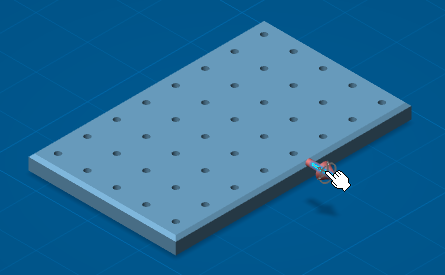
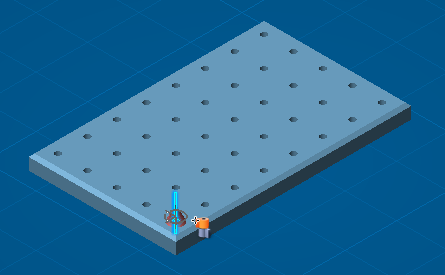
- When you move the first component over the second component, 8 solutions have been found according to their publications:
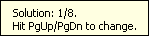
Tip: Use Page Up or Page Down keys to select another solution.
The Engineering Connection Definition dialog box is updated.
\The first component Axis
 is selected.
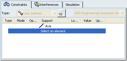
Important: The selection order of components is taken into account.
- When there is no solution or while you have not move the first component over the second component:
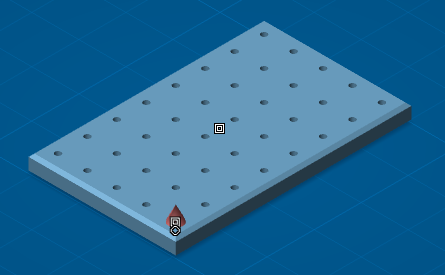
Move the cursor over a solution will show a pre-positioning with the closest solution found.
Important: The Revolute
 cursor is displayed. The type of cursor depends on the published geometries.
Move the cursor over the desired solution and click with the mouse.
The component is positioned and constrained.
The Engineering Connection Definition dialog box is updated.
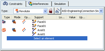
A Contact and a Coincidence constraints have been created using publication names as supports.
Important: While the Positioning Mode option is on
 , no engineering connection is created although you click
OK in the
Engineering Connection Definition dialog
box.
, no engineering connection is created although you click
OK in the
Engineering Connection Definition dialog
box.