Engineering Connection Definition Dialog Box | ||
| ||
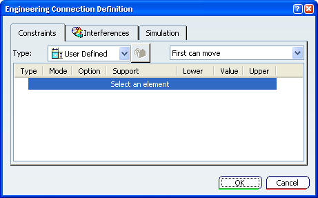
Constraints
- Type
- The options in the
engineering connection Type are as follows:
 User Defined
 Rigid
Rigid Spherical
 Cylindrical
 Planar
 Prismatic
 Revolute
 Screw
Screw Point Curve
 Point Surface
-
 Gear
Gear  Rack
Rack Cable
Cable Universal
 Roll Curve
 Slide Curve
 Fix
Fix Free
Free-
 Symmetry
 -
 Projection.
This engineering connection is used typically for positioning of a Spot Fastener Instance (see CATIA : Mechanical : Fastener Design for further information on Spot Fasteners).
 Pattern
Important: - The engineering connection type is defined by a combination
of Driving
 constraint and Controlled
  constraint.
The engineering connection type is automatically detected when its Driving constraints respect its definition.
- A constraint can be deactivated. In this case it is not
taken into account during the PLM update.
A deactivated mask (red parentheses) appears on the upper left corner
 .
.
- Examples of the Driving constraint relation in Engineering Connection Type above are not necessarily exhaustive.
- Lock or Unlock an Engineering Connection Type
- When you are creating an engineering connection, the
Type field is updated according to the
created constraints.
-
 Lock: The engineering connection type is
locked. Modification of constraint definitions outside the engineering connection type
definition is possible, but the engineering connection type will be detected in
error during the PLM update.
Lock: The engineering connection type is
locked. Modification of constraint definitions outside the engineering connection type
definition is possible, but the engineering connection type will be detected in
error during the PLM update. -
 Unlock: The engineering connection type
is unlocked. The
Type field is updated according to
constraint definition modifications.
Unlock: The engineering connection type
is unlocked. The
Type field is updated according to
constraint definition modifications.
Note:
If you are a DS Passport Customer, you can read the Knowledge Base for more about Revolute behavior in Lock and Unlock modes.
-
- Engineering Connection Templates
- According to the selected engineering connection type,
Engineering Connection Templates
 displays the constraints, constraint modes and constraint elements needed to
define the engineering connection type.
displays the constraints, constraint modes and constraint elements needed to
define the engineering connection type.Important: - Using this option you can create an engineering connection from scratch, then select the geometry.
- This option can be enabled after you lock the engineering connection type; in this case missing constraint is proposed.
- Constraint Definition
-
- Constraint Type
- The following constraints can be created according to the
context type, from a contextual menu:
- Insert a constraint:
-
 Contact
-
 Fix together relatively
-
 Fix together
-
 Coincidence
-
 Offset
- Angle
-
 Angle
Angle
-
 Parallelism
-
 Perpendicularity
-
 Hinge
Hinge
-
-
Curve
-
 Curvilinear distance
-
 Roll
Roll
-
 Slide
Slide
-
-
 Symmetry
-
 Coupling
See also Coupling Dialog Box.
-
 Fix
Fix
-
 Fix in space
-
- Delete the constraint.
- Replace the constraint by
another one.
Important: When elements defining the constraint are not compliant with the new one, a warning message appears, the previous constraint is deleted and you have to select new geometries.
- Deactivate the constraint. In this case the constraint is not taken into account during the PLM update.
- Insert a constraint:
- Constraint Mode
- This column displays the constraint icon. Three modes are
available:
-
 Driving: the constraint definition
is applied during the PLM update.
Driving: the constraint definition
is applied during the PLM update.
-
 Measured: the constraint value is
deducted from its definition and other constraints of the engineering
connection during the PLM update.
Measured: the constraint value is
deducted from its definition and other constraints of the engineering
connection during the PLM update.
-
 Controlled: defines the constraint
controlled by the user in the kinematics relation. The constraint value is
defined between bounds.
Controlled: defines the constraint
controlled by the user in the kinematics relation. The constraint value is
defined between bounds.
Important: When a constraint leads to an unpredictable state, a warning mask
 will appear on all controlled constraints.
-
- Constraint Options
- This column displays the constraint geometry option and is filled
only when the orientations of the selected elements are taken into account in
the constraint definition:
- For a plane:
-
 Undefined: the plane orientations
are undefined and can be modified during the PLM update.
Undefined: the plane orientations
are undefined and can be modified during the PLM update.
Important: Leaving the plane orientations undefined may allow an inversion of the components repositioning during:
- PLM update process,
- or move under constraint,
- or using Assembly Design Manipulation command.
-
 Same Orientation: the plane
orientations are the same.
Same Orientation: the plane
orientations are the same.
-
 Opposite Orientation: the plane
orientations are opposite.
Opposite Orientation: the plane
orientations are opposite.
-
- For a line:
-
 Undefined: the line orientations are
undefined and can be modified during the PLM update.
Undefined: the line orientations are
undefined and can be modified during the PLM update.
-
 Parallelism: the lines are parallel
but not oriented.
Parallelism: the lines are parallel
but not oriented.
-
 Same Orientation: the line
orientations are the same.
Same Orientation: the line
orientations are the same.
-
 Opposite Orientation: the line
orientations are opposite.
Opposite Orientation: the line
orientations are opposite.
-
- For a hinge:
-
 Direct Angle
-
 Angle + 180deg
-
 180deg - Angle
-
 360deg - Angle
-
- For an axis system:
-
 x axis
-
 y axis
-
 z axis
-
- For a plane:
- Lower
- This column displays the lower constraint value for an angle or
an offset.
This value is used for a constraint in Controlled mode.
- Value
- This column displays the constraint value for an angle or an
offset, or the ratio%offset value for a coupling.
Important: A value may be unset to leave the value unspecified.
- Upper
- This column displays the upper constraint value for an angle or
an offset.
This value is used for a constraint in Controlled mode.
- Constraint Support
- This table displays the constraint support:
Element/Geometry Icon Axis system 
Circle 
Cone 
Continuous curves 
Curve
Cylinder 
Edge 
Face 
Line (from Generative Shape Design)
Plane (from Generative Shape Design)
Point (from Generative Shape Design) 
Product 
Sketch containing continuous curves
Sphere 
Surface 
Vertex
Important: - Some masks can be displayed on the support icon:
Status OK Warning Error Free


Locked 


Published 


Locked & Published 


- A support is automatically locked when the engineering
connection is created or when you click Engineering connection templates
.
- Some masks can be displayed on the support icon:
![]()
Interferences
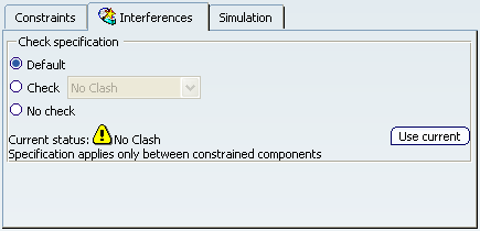
| Important:
You can only access the Interferences tab for the configurations or products you installed and for which you have a license. |
- Check specification
- The options in the
Check specification are as follows:
- Default: no interference specification has been defined in the engineering connection.
- Check:
- No clash: checks clash between components involved in the engineering connection.
- Contact: checks contact between components involved in the engineering connection.
- Clearance: checks the minimal clearance between components involved in the engineering connection with the defined value.
- No check: do not check interference.
![]()
Simulation
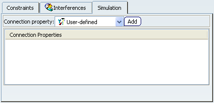
| Important:
You can only access the Simulation tab for the configurations or products you installed and for which you have a license. |
- Connection property
-
The options in the
Connection property are as follows:

Distant Creates a distant connection property.

User-defined Creates a user-defined connection property.

Face face Creates a face face connection property.

Fastened Creates a fastened connection property.

Bolt tightening Creates a bolt tightening connection property.

Spot weld Creates a spot weld connection property.

Seam weld Creates a seam weld connection property.

Curve curve weld Creates a curve curve connection property.

Surface weld Creates a surface weld connection property.
- Add
- Opens the User-defined Connection Property dialog box in order to create a user-defined connection property.
- Connection Properties
- Display the list of connection properties in the Engineering Connection.