Snapping Components in an Engineering Connection | |||||
|
| ||||
Click Engineering Connection
 .
.
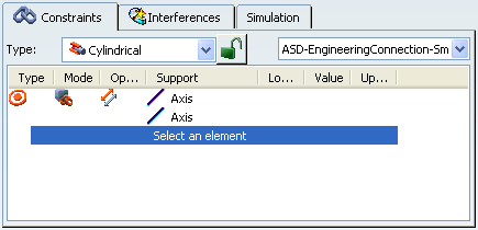
The Engineering Connection Definition dialog box and the Engineering Connection Assistant toolbar appear.
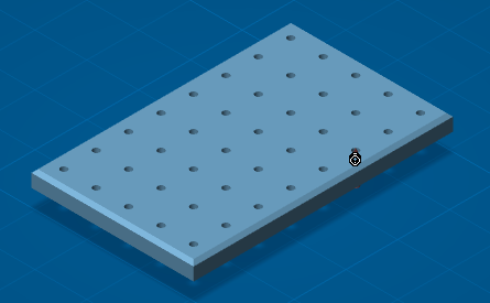
Important: Be sure that the Smart Positioning
 option is not selected.
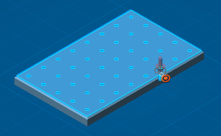
The assembly looks like this:
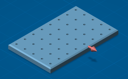
Select the first component.
The snap capability is initialized. The Engineering Connection Definition dialog box is updated.
The first component Axis
 is selected.
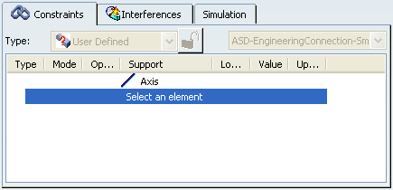
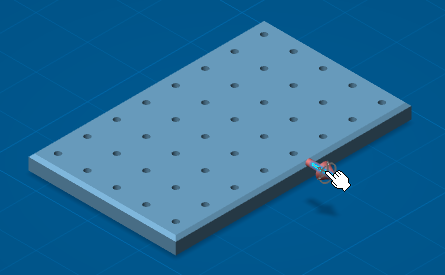
Move the mouse over the geometry of a second component.
According to the selected geometrical elements in the first component, the first component is pre-snapped on the compliant geometries of the second component.
Important: - The Coincidence
 cursor is displayed. The type of cursor depends on the selected geometries.
 - The constraint order is defined in . See Constraint.
- The Coincidence
Select a compliant geometry on the second component and click the left button of the mouse
The snap is validated and a constraint is created.
The Engineering Connection Definition dialog box is updated.
Important: While the Positioning Mode option is on
 , no engineering connection is created although you click
OK in the
Engineering Connection Definition dialog
box.
, no engineering connection is created although you click
OK in the
Engineering Connection Definition dialog
box.
Click OK in the Engineering Connection Definition dialog box to create the engineering connection.
The assembly looks like this: