Creating an Assembly Cut | |||||||||
|
| ||||||||
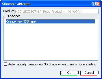
The Choose a 3DShape dialog box appears:

The Choose a 3DShape dialog box displays:
- In the
3DShapes list:
- By default, the list of available and editable 3D shapes in the active product, otherwise the list of available and editable 3D shapes in a selected product.
- The Create new 3DShape option.
- The Automatically create new 3D Shape when there is none existing option which allows you to launch directly the 3D Shape / Representation DS dialog box only when no representation exists under the active product.
- In the
3DShapes list:
Select Create new 3DShape in the 3DShapes list and click OK.
The 3D Shape / Representation DS dialog box appears.
Important: When you create a new 3DShape its Nature is set as Specification, whatever nature you are selecting in the 3D Shape / Representation DS dialog box, but you can modify this nature after the 3DShape creation by editing its properties.
Click OK in the 3D Shape / Representation DS dialog box.
Select the geometry in the assembly where you want to create the split features.
Important: A warning message is displayed when you select a geometry outside the active 3D Shape; the selected geometry does not belong to the current functional body.
This configuration will create a link between functional body, and this message means that you are creating a link between the 3D shape functional body containing the assembly feature and the body element which support the feature.
Click OK in the Warning dialog box.
- You are now in the Assembly Specification workshop.
- The
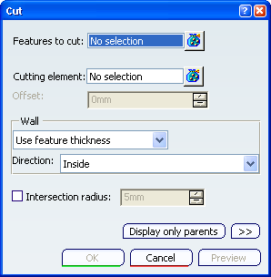
Cut dialog box appears:

Important: Only the Cutting elements field is taken into account in an Assembly Split, whatever you fill or select for other options.
- The
Creation toolbar appears:

-
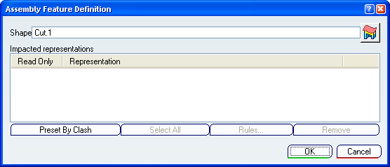
 Launch Assembly Feature Definition:
this option displays the
Assembly Feature Definition dialog box
at the end of the 3D shape feature creation.
-
 Specification in No Show: this option
swaps to hide/show the 3D shape feature at the end of its creation.
-
Select the Cutting element field and select cutting elements.
Specify the cut properties then click OK in the Cut dialog box.
The Assembly Feature Definition dialog box appears.

Select in the specification tree 3D shapes that will be affected by the cut feature.
Products are added to the affected list of the Assembly Feature Definition dialog box.
Click OK in the Assembly Feature Definition dialog box.
- You exit the Assembly Features workshop.
- The Assembly Split is created.
- A solid linked to the Assembly Split is created in the representation of each affected representations.
Click Update All
 to display the cut feature.