Creating Single Annotations

You can generate and attach a single functional annotation to a given fastener in order to display the fastener's parameters.

This task shows you how to:


Before you begin: Create a Creating a Fastener Setwhose Process Category (PTYP1) is set to Weld and Process Type (PTYP2) to Resistance (21) and a Creating a Spot fastener within this fastener set.
Related Topics
About Functional Annotations
abf-m-FunctionalAnnotation-sb.htm

Customize the Field Display

You can customize the default parameters for each field.

They can be customized through the Fst_Standard file:


  • Customize the following parameters that are assigned to the fastener annotation:


    • F1 displays fastener ID
    • F2 displays the Robustness value
    • F3 displays the Finish value
    • F4 displays the diameter value
    • F5 displays the joined product instance names

Customize the Symbol Display

You can customize the display of the symbol.

  • For each Process Category and Process Type, define a standard parameter in order to customize the fastener symbol (B1 and B4 only): FTYP_FTASYMBOL_FTY_PCA_PTY, where FTY = Feature Type, PCA = Process Category and PTY = Process Type.

Create Single Annotations

You can create single annotations.

  1. Click Spot Fastener Annotation in the Fastener Annotations toolbar.

  2. Select the spot in the 3D area or in the specification tree.

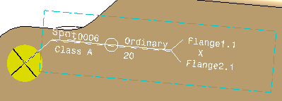
    The annotation anchor point will be positioned according to the fastener's location, i.e. at the location point for a spot fastener.

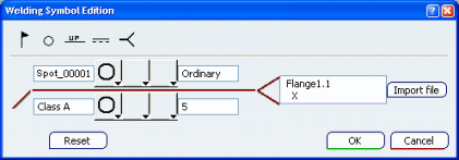
    The Welding symbol edition dialog box is displayed.


    B1 and B4 symbols are displayed according to the values set in the Fst_Standard file (Welding Symbol: 13). Other symbols can be manually defined.

    Tip: If the field F5 is assigned to User Value (defined by the value "USR"), you can click Import file to set it by importing a reference text file.

  3. Click OK to create the annotation.