About Functional Annotations | ||||||
|
| |||||
Choice of Fastener Parameters for Each Field
Fastener parameters to display in a given field Fi (where i=1, ...5) have to be chosen among the list of possible parameters, as defined in the Fst_Standard file:
- Reference Fastener Type parameters
- Process Type
- Component Material Name
- Fastener definition parameters
- Fastener identifier
- Fastener classification parameters:
- Design Parameters: Robustness, Regulation, Finish
- Manufacturing Parameters: Geometry flag, Inspection flag
- Custom Parameters (for instance: U01)
- Fastener Shape Parameters:
- Diameter
- Diameter, Length, Head Diameter, Head Length, Foot Diameter, Foot Length
- Concatenation of fastener parameters
- Process Type (Robustness)
- Joined contact zones information parameters:
- Joined product instance names (JPN)
- Joined zone names (JZN)
- Joined zone material/ thickness (JZTHKMAT)
- Zone Count (ZoneCount)
- Joined product instance names + Zone count (JPN- ZoneCount)
- Joined zone names + Zone count (JZN- ZoneCount) Joined zone material/ thickness + Zone count (JZTHKMAT- ZoneCount)
- Free user value (USR): no value is displayed in the associated Field; you can freely set the value to display.
![]()
Symbols
From the Welding creation dialog box, you can assign an annotation symbol to each annotation button using the combo lists:
B1 (Up Left Symbol), B2 (Up Middle), B3 (Up right), B4 (Bottom Left), B5 (Bottom Middle) and B6 (Bottom Right):

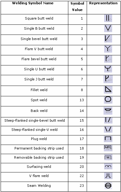
Only symbols SYM1 and SYM4 (corresponding to B1 and B4) can be defined in the Fst_standard file. They are to be chosen among the list of possible symbols, depending on the Tolerancing Standard:

Other symbols (B2, B3, B5 and B6) can be manually specified by the user.
![]()
View Planes
Annotation planes are created in the view plane and visualized by default in the activated annotation view.
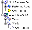
In the specification tree, it is created under the Welds node:

If there is no activated annotation plane during the annotation creation, an annotation plane is automatically created by default parallel to the xy plane.
![]()
Modification and Edition of an Annotation
Functional annotations (except for datum annotations) are associative with their attached fasteners:
- if you modify the fastener location and update the product, the annotation is automatically re-positioned and updated.
- if you modify the fastener's parameters (joined parts, ID, process type, etc.) and update the product, the attached annotation text is automatically refreshed.
- if you delete the fastener and update the product, the attached annotation is automatically deleted.
-
if
you select the fastener, all associated annotations are highlighted
both in the 3D area and in the specification tree, providing
3D-Annotation-Query Switch On/Switch Off
 is activated.
For further information, refer to Querying 3D Annotations in the 3D Functional Tolerancing & Annotation User's Guide.
- You can modify an annotation either by:
- changing its position:
- transferring it into another annotation plane
- moving it through drag and drop
- mirroring
- deleting it
-
editing its parameters:
- associative annotations: all the fields can be modified. However, if you modify by mistake a value set to an ABF attribute, the correct value is automatically restored once you update or check the corresponding fastener.
- datum annotations: all fields and drafting symbols can be modified.
- modifying the visualization plane of the annotation text
- changing its position:
- You cannot move an annotation independently from its annotation plane.
![]()
Datum Annotation
You can create a datum annotation by clicking Create Datum
![]() before
validating the annotation.
before
validating the annotation.
- Datum annotations are not associative with their attached fasteners: if you modify a fastener's parameter (location, process category, process type, etc.) and update the product, it has no impact on the datum annotation.
- Datum annotations can be moved anywhere in the geometry area as it always remain in the annotation plane.
- They have a particular display (red cross) in the specification tree:

Warning: An associative annotation cannot be isolated, that is changed to a datum annotation.
For more information about the Datum mode, refer to Creating Datum Elements in the Generative Shape Design User's Guide.
![]()
Miscellaneous
Here are miscellaneous information regarding annotations.
- You can select several fasteners belonging to the same reference fastener type in order to create one functional annotation for each selected fastener at a time. If among the selected fasteners, one fastener corresponds to a reference Fastener Type different from the reference fastener (that is the first selected fastener), a warning message is displayed explaining that the selected fastener is not valid. When you click OK, the command remains applicable to fasteners having same the fastener type as the reference fastener.
- The annotation name is set from its associated fastener name (for
instance, Spot_00000 for the first created annotation and Spot_00000 (2) for the
second created annotation):

- If the engineering class parameter of a fastener is set to Unspecified Value (defined by the value "UNSPEC"), the field corresponding to the associated annotation will not display any value.
- If a field is associated to a fastener parameter (that is different from "User Value"), you are advised not to manually modify it. Indeed, this field will be associative with the fastener parameter. Nevertheless, if you modify by mistake this field value, when clicking OK at the creation of the annotation or at the next update, the former associated values will be automatically restored.