Creating a Fastener Set | |||||
|
| ||||
Create a Fastener Set
You can first create the fastener set.
Click Fastener Set
 in the Fastener Creation toolbar.
The Product / Product DS dialog box opens.
Click Finish.
The Fastener Set Definition dialog box opens.
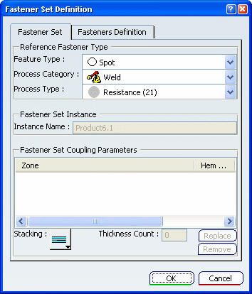
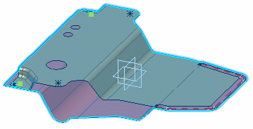
Select the zones to be joined in the specification tree or in the 3D area.
Tips: - You can apply a core material on a 3D shape representation or
feature by
clicking Apply Core Material
 .
For more information, refer to
Material Definition User's Guide : Applying Materials : Applying a Core Material.
.
For more information, refer to
Material Definition User's Guide : Applying Materials : Applying a Core Material.Note: if you modify or add a material applied on a zone, it is not automatically updated on the published element and not taken into account by the fastener set even after having updated it.
- You can define a thickness and an orientation on a 2D or 3D geometric element using the Thin Parts Attribute command. For more information, refer to Generative Shape Design User's Guide : Using Tools : Applying a Thickness.
- You can select either a 3D shape representation as an unspecified zone or a published element as a published zone. Note that zones should be selected only within or at a lower level of the fastener set.
Warning: - You can only publish surfaces or solids as zones. Selecting a
publication which is not a surface or a solid will not be taken
into account.
Note that:
- If the selected object is the PartBody (and even it is already published), its 3D representation will be highlighted and chosen as the zone. Otherwise, only surfaces or solids (or their publications) may be selected.
- If the object is already published, the closer port to the fastener set in the specification tree will be chosen as the zone. If you want to select a particular port publishing a geometric element, you need to explicitly select it.
- If you try to select an isolated publication (marked as "Disconnected" in the Zone area) or replace an existing zone by an isolated publication, an error message is issued prompting you to select another publication.
- If you right-click a zone to select a publication, isolated publications are never displayed in the contextual menu.
- You can apply a core material on a 3D shape representation or
feature by
clicking Apply Core Material
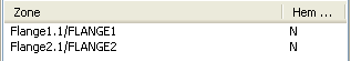
If necessary, define a zone as the hemmed zone by simply selecting it in the zones list. It is set to "Y" and the Stacking type is automatically set to
 . By default, no hemmed zone is specified.
Important: - You can switch the Stacking type, between Lap
 or
Hem
.
or
Hem
. - If you have set the Stacking type to Hem, switching to Lap will remove the duplicated zone (i.e. hemmed zone).
- The Thickness Count value is automatically computed according to the number of joined zones and cannot be modified.
- You can switch the Stacking type, between Lap
From the Fasteners Definition tab, modify the values of Design, Manufacturing and Custom parameters.
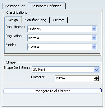
Important: All fasteners of this fastener set will be created according to these parameters, except if some parameters are overloaded for specific fasteners.
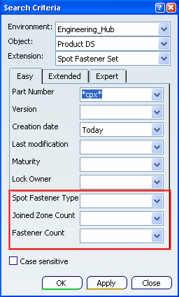
In the specification tree, the Spot Fastener Set node is created:
It includes all specified fastening rules that can be Editing and Modifying Fastening Rules.
| Important: When you have not defined any user preferences, the default reference fastener type is determined from the Fst_Standard file. |
![]()
Save to the Database
You can propagate your modifications to the database.
Select PLM Access > Propagate... or click Propagate
 in the Bar.
The Propagate dialog box opens and displays all references.


![]()
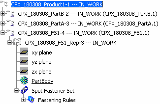
Search Fastener Sets
You can search for fastener set objects in the database by defining search criteria for chosen object attributes.
Fill in the Part Number field and Creation Date as search criteria:
Tip: You can use the following ABF attributes associated to the Spot Fastener Set as a search criteria: - Spot Fastener Type
- Joined Zone Count
- Fastener Count
Click Apply to launch the query and OK to close the Search Criteria dialog box.
Results are displayed along with the attributes used as search criteria, if defined.

Right-click the representation and select the Edit > Properties contextual command.
The Properties dialog box opens:
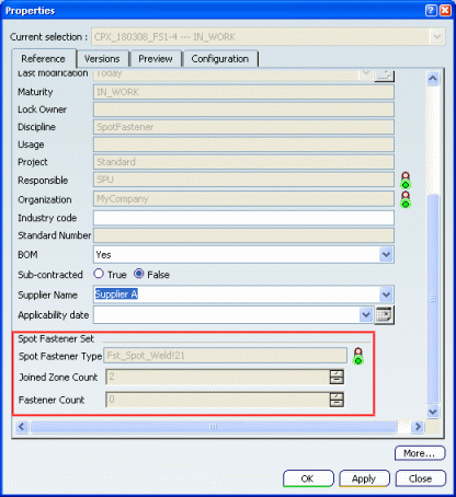
You can see that ABF attributes are displayed according to the selected Extension (Spot Fastener Set).
![]()
Examine Impacts
You can edit links contained in your product.
For the case of a selected PLM Fastener Set, it enables to check for Fastener Set Joined Parts and impacted Fasteners.
Select Edit > Links & Relations or click
 in the Bar.
The Edit Links & Relations dialog box opens.
Select Graph with Details as the View.
The graph representation shows the "Impacted by" dependency relation between the fastener set and the joined parts ("Fasten" links).The list details the role and status of the links, as well as pointed elements and pointing elements.

