Graphic Replacement for Plates | ||||
|
| |||
The sample XML file provided with this application is Structure_GVS.xml.
This file is located at ../OS/resources/standard/generativeparameters.
Generative view styles are defined by an administrator and specify the appearance and behavior of a generated view. Generative view styles are defined in an XML file. For more information on GVS, refer to Generative Drafting User’s Guide: Generative View Style: About Generative View Styles.
The reference planes that will be used for a given project are defined in an XML file pointed by a Project Resource Management resource, Reference Plane System. For more information, please refer to Reference Plane System.
For more information about how to create views using generative view styles, how to set generative view style parameters or more generally on administering generative view styles, please refer to the Generative Drafting User's Guide: Generative View Style.
You can customize generative view style parameters for the reference plane system. These parameters are shared by all structure applications.
![]()
Sample XML File
In the sample XML file, generative view style parameters for plates are located towards the bottom of the file under StructureObjects.
Plate
- Draw
- Yes extracts the object. No indicates the object will not be extracted.
- GraphicReplacement
- Indicates whether to use graphic replacement. Yes or No.
- Angular Tolerance
- To trigger this type of view in degrees. Default value is 15.0.
- LogicalViewGeneration
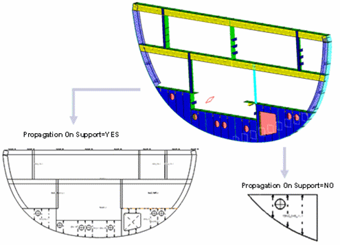
- PropagationOnSupport
- To use the propagation on Super Plates. Yes indicates propagation will be used. No is the default; no propagation will be used (will project 3-D only).

- OffsetTolerance
- Offset value used to include or exclude objects using the same support with different offsets. Default value is 0.0.
- ViewType
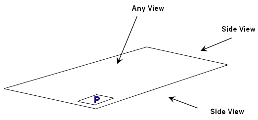
- There are two view types for plates: SideView and AnyView.

Each have NearSide and FarSide parameters, and AnnotationTextStyle parameters. SideView also has MaterialExtrusionSymbol parameters.
Important: Logical and Functional Tolerance and Annotation (FTA) Section are the only modes, where you can compute AcrossSide parameters, which are similar to NearSide and FarSide parameters. The default values are same as NearSide values. If you are not interested in an AcrossSide analysis, you need to synchronize Near and Across Linetype and LineThickness. - MaterialExtrusionSymbol
- Draw
- Draws the material throw orientation. Yes or No.
- MaterialExtrusionMode
- Draws the material throw orientation. Values are:
1 = Tick mark (true width)

2 = Throw orientation (symbolic)

3 = Tick mark and throw orientation

- SymbolLocation
- The location on the line representation of the plate where the throw orientation will be drawn. Values are:
1 = Start
2 = Middle
3 = End
- MaterialThroughOrientationSymbol
- ChapterName
- The name of the chapter containing material through orientation symbols within the Drawing Symbol Structure Catalog.
- SymbolName
- The symbol name to draw.
- ReferenceScale
- Scale factor to apply to the symbol as drawn. Default is 1.
- TickMarkSymbol
- Length of tick mark when drawing a tick mark. Default is 5.0 millimeters.