More About Creating a Stiffener | |||||
|
| ||||
Support
This topic provides information about the support for stiffeners.
The support selected should be compatible with the category defined.
Curves can be also selected as a support for stiffeners. Image below shows the stiffener created with the curve as a support.
![]()
Angle
This topic provides information about the angle of stiffeners.
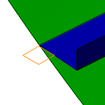
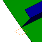
When a stiffener is created using the Along plane option, it retains the angle of the support that was selected. The stiffeners created using the Normal to plate option have an angle that is normal to the plate on which they are placed.
The images below show stiffener placed on a shell supported by a horizontal deck plane.
Along plane
 |
Normal to plate
 |
Note: When creating a stiffener using a curve as a support, the Along plane angle has no effect. You can use the Normal to plate option.
![]()
Orientation
This topic provides information about the orientation of stiffeners.
Use Flip button in the Plate Side box to toggle the stiffener from one side of the plate to the other.
 |
 |
Use Flip button in the Section Orientation box to toggle the section.
|
 |
The anchor points that display in the Anchor Point box are defined in the file MoldedConventions.xml.
![]()
Creation of Multiple Stiffeners
This topic provides information about the creation of multiple stiffeners.
It is possible to create several other stiffeners after defininng limits for one stiffener. All these stiffeners have the same limits as the first stiffener.
You can create several stiffeners using one of the following methods:
- Right-click the Support box and choose Select Reference Planes. The Plane Systems dialog box appears. Select the planes/crosses (Ctrl - click) to define the locations of additional plates.
- You can also select planes (or other objects) in your design to define the location of additional stiffeners.
- Create a grid, and select the lines of the grid to define the location of stiffeners.