Geometry | ||||||
|
| |||||
Geometry
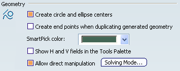
- Create circle and ellipse centers
-
Select this check box if you want to create centers when creating circles or ellipses.
 By default,
this option is selected.
By default,
this option is selected. - Create end points when duplicating generated geometry
-
Select this check box if you want to create end points when duplicating geometrical elements that were generated from the 3D.
By default,
this option is not selected. - SmartPick color
-
Select the color that will be used to define SmartPick elements from the drop-down list.
By default,
the color is set to green. - Show H and V fields in the Tools Palette
-
Select this check box to show the H and V fields in the Tools Palette when creating 2D geometry or when offsetting elements.
Leaving the option clear enables you to directly enter the value corresponding to the type of element you are creating: for example, the length when creating a line, the radius when creating a circle or the offset value when offsetting elements.
Important: When a command (such as the Point creation command) does not have any parameters other than H and V, then these two fields will remain in the Tools Palette, whether you select this option or not.
By default,
this option is not selected. - Allow direct manipulation
-
Select this check box to be able to move geometry using the mouse. When moving geometry, you can move either the minimum number of elements, the maximum number of elements, or still the minimum number by modifying the shape of elements, if needed.
Click Solving mode... to configure direct manipulation in the Dragging of elements dialog box. Refer to Dragging Of Elements Dialog Box for more information.
By default,
this option is selected.
![]()
Constraints creation
- Create detected and feature-based constraints
-
Select this check box if you want the geometrical or dimensional constraints detected by the SmartPick tool to be created.
This option is also available in the Tools toolbar through Create detected constraints
 .
.
If you leave this check box clear, Create detected constraints will be inactive by default. You will be able to activate it at any time.
By default,
this option is not selected. - SmartPick...
-
As you create more and more elements, SmartPick detects multiple directions and positions, and more and more relationships with existing elements. This may lead to confusion due to the rapid highlighting of several different detection possibilities as you point the cursor at different elements in rapid succession. Consequently, you can decide to filter out unwanted detections.
Click this button to configure SmartPick. Refer to SmartPick Dialog Box for more information.
![]()
Constraints Display
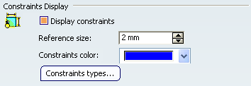
- Display constraints
-
Select this check box to visualize the logical constraints specific to the elements.
Clearing this option disables the other options in this category.
By default,
this option is selected. - Reference size
-
Specify the size that will be used as a reference to display constraints symbols. Changing this reference size will modify the size of all constraints representations.
By default,
the reference size is set to 2 mm. - Constraints color
-
Choose the color that will be used to display constraints.
By default,
the color is set to blue. - Constraints types...
-
Click this button to define which types of constraints you will visualize as you create geometry. Refer to Constraints Types Dialog Box for more information.