Display | |||||
|
| ||||
Grid
- Display
- Select this check box to display the grid. This option is also available in the Visualization toolbar.
Note: When the sheet frame is displayed in the drawing, the grid is displayed within the sheet frame. When the sheet frame is not displayed in the drawing, the grid is displayed in the entire window.
 By default,
this option is selected.
By default,
this option is selected. - Snap to point
- Select this check box if you want geometry (as well as 2D components)
to begin or end on the various intersection points of the grid.
Note that this option is also available via the Tools
toolbar.
By default,
this option is selected.
- Allow Distortions
- Select this check box to apply different graduations and spacing
between H and V.
By default,
this option is not selected.
- Primary spacing: H and V
- Enter the values of your choice in the H
and/or V fields to define the horizontal and vertical spacing between the major lines of the grid.
By default,
primary spacing is set to 100 mm.
- Graduations: H and V
- Enter the values of your choice in the H
and/or V fields to set the number of graduations between the major horizontal and vertical lines of the grid,
which actually consists in defining a secondary grid.
By default,
graduations are set to 10.
![]()
Specification Tree
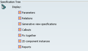
- Parameters
-
Select this check box to display in the specification tree the formula parameters used in
the drawing.
By default,
this option is selected.
- Relations
-
Select this check box to display in the specification tree the relation parameters used in the
drawing.
By default,
this option is selected.
- Generative view specifications
- Select this check box to display generative view specifications in the specification tree, such as:
- auxiliary view
- breakout
- broken
- clipping (exact or quick clipping)
- 3D clipping (box, slice or back-plane)
- detail view (circular or polygonal profile)
- offset or aligned section view or section cut
By default,
this option is selected.
- Callouts
- Select this check box to display callouts in the specification tree.
- auxiliary callouts
- section callouts
- detail callouts
By default,
this option is selected.
- Fix together
- Select this check box to display Fix together constraints in the specification tree.
By default,
this option is selected.
- 2D component instances
-
Select this check box to display 2D component instances in the specification tree.
By default,
this option is selected.
- Reports
- Select this check box to display reports such as bill of material in the specification tree.
By default,
this option is selected.
![]()
Elements Analysis
- Activate elements' analysis
- Select this check box to display elements (such as dimensions, geometries, callouts, weldings and patterns) using different colors according to their types.
- Click Configure to configure elements' analysis in the Element's Analysis dialog box. Refer to Element's Analysis Dialog Box for more information.
By default,
this option is selected.
- Activate geometries' diagnostic
- Select this check box if you want over-constrained, inconsistent, not-changed or iso-constrained elements to be identified using specific colors.
- Click Configure to configure geometries' diagnostic in the Geometries' Diagnostic dialog box. Refer to Diagnostic Colors Dialog Box for more information.
By default,
this option is selected.