Create Product Flow Links
You can create the product flow links between two systems in the Live System Editor.
Select a system (for example, a Source system) in Live System Editor.
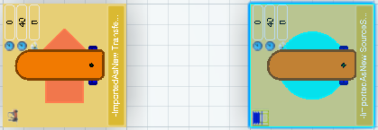
Click Create a Product Flow command. command. Select a second system (for example, a Transfer system).
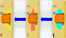
A message Product Flow created successfully appears to inform that the product flow link is created between the Source and Transfer systems. In this way you can create product flow links between different systems in the Live System Editor.

Define Product Flow
You can easily define the product flow
and flow behavior between selected systems. You can also create operations and ports, link between ports, link between ports and operations, link between operations and ports, and edit flow details (priority/proportion and so on).
Click Define Product Flow  command. command. The Define Product Flow dialog box appears.
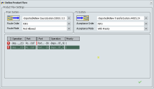
Select the system either from From\To System drop-down menu or click  and and  and then select source\target system in the PPR Context\authoring window. and then select source\target system in the PPR Context\authoring window. - Select the system from which you want to define product flow in From System drop-down menu.
- Select the target system to which you want to define product flow in To System drop-down menu.
Note:
The From System and To System cannot be same. A message appears if you specify the same system in both.
Select the routing order, in which products are routed out of the system, in Route Order drop-down menu.
- FIFO: First in First out
- LIFO: Last in First Out
- Priority: This is a system attribute.
Specify the route mode, to select the downstream system to which a product is routed, in Route Mode drop-down menu.
- First Allowed: This is an attribute of a system. The product/request is routed to any destination (that is, any system that accepts the product).
- In Proportion: This is an attribute of a system. A product/request is randomly routed to any of the allowed destinations. The destination is chosen as per the given proportion.
- With Priority: This is a system attribute. A
product/request is routed to the highest priority destination that
accepts the product at the given time. If two product flow links have equal priority, then based
on simulation behavior, the system which has first sent a request
will receive the product.
Specify the Acceptance Mode to select the upstream system from which a product may be accepted. Specify the Acceptance Order in which products are accepted at the system. Specify or create new Operation for the selected systems. - Double-click cell under Operation row and select the required operation of the selected system from drop-down menu.
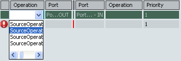
- Select Create Operation from drop-down menu to create a new operation for the selected system.
The Create New Operation option is available for Buffer, Transfer, and Sink systems. Create General Operation and Create Loading Operation options are present for General and Transformation systems.
The  is displayed on the modified\new rows till you click Apply is displayed on the modified\new rows till you click Apply  . . Select or create a new port for the selected systems. - Double-click cell under Port row and select required port of the selected system from drop-down menu.
Port is an object through which the material flows.
- Select Create IN Port\Create OUT Port from drop-down menu and enter the port name in cell to create a new port.
Double-click Priority/Proportion row and edit the priority/proportion value. Click Apply  to apply the flow details. to apply the flow details.

Create Flow Connection
You can create a flow connection between two objects. The link can be created between an operation and
a port, between two ports, or between a port and an
operation.
To link an operation to a port only for one system. - Select a system in From System and select None in To System or vice-versa.
- Select the cell under the Operation column and select operation
from the drop-down menu.
- Select the cell under the Port column and select the required port
from the drop-down menu.
- Click Apply
 to link an operation to a port. to link an operation to a port.
To link an operation to a port between two systems. - Select a system in From System and To System.
- Select the cell under the Operation column and select operation
from the drop-down menu.
- Select the cell under the Port column and select the required port
from the drop-down menu.
- Click Apply
 to link an operation to a port. to link an operation to a port.
To link a port between two systems: - Select a system in From System and To System.
- Select the cell under the Port column for both From\To System and select the required port
from the drop-down menu.
- Click Apply
 to link a port between two systems. to link a port between two systems.

Detail Product Flow and Flow Behavior between Two Systems
You can preview and edit the product flow
and flow behavior in
Live System Editor between two selected systems. The Detail Selected Material Flow Link command terminates if the
selected system has no operations or if it is not connected to any
of the downstream systems.
Double-click product flow link between two systems in
Live System Editor. See Using Live System Editor The balloon toolbar appears.
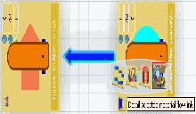
Select Detail Selected Material Flow Link  in the balloon toolbar. in the balloon toolbar. The Define Product Flow dialog box appears.
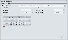
Make the necessary changes as described in Define Product Flow, if required.
|
![]()
![]()
![]()


 and
and  and then select source\target system in the PPR Context\authoring window.
 is displayed on the modified\new rows till you click
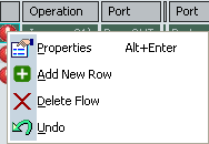
 appears in row for which the flow connection is deleted.
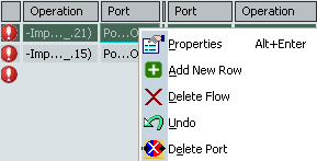


 in the balloon toolbar.