Creating All Prismatic Machinable Features | ||
| ||
Create All Prismatic Machinabe Features from the Geometry
You can prepare a design part for manufacturing by automatically creating all recognizable prismatic machinable features from their geometry.
Activate the Manufacturing Program and click Global Feature Recognition
 in the Axial Machining Operations toolbar.
The Global Feature Recognition dialog box appears.
Select all the Feature check boxes so that the part is analyzed for all machinable feature types.
Depending on which features you want to create, proceed as follows:
- To create axial machining features only, select the Hole check box.
- To create prismatic machining areas only, select all the check boxes except the Hole check box.
- To create all holes included in a tab hole, select the Enable creation of tab hole components check box. A tab (or tabulated) hole is more complex than a Part Design hole in that its hole chain (that is, all faces) do not match a Part Design feature. If the check box is not selected, the holes belonging to the tab holes are not created (default behavior).
-
If the Hole check box is selected, the Only for existing Tech. Result and Only for non existing Tech. Result checkboxes become available for selection.
- If Only for existing Tech. Result check box is selected, machinable axial features are created only for holes of the selected body with technological results.
- If Only for non existing Tech. Result check box is selected, holes without associated technological results are recognized.
Feature recognition also provides a Prismatic Machining Area corresponding to a Complex Pocket. The boundary is defined by a hard boundary only. An imaginary contour at the intersection of Hole and Slot, is automatically defined to close the hard contour. But this imaginary contour is shown only when hole is recognized by Prismatic Machining Preparation Assistant. In this way V6 would give correct minimum and maximum channel width values for prismatic machining area.
Go to Advanced tab to specify a number of parameters for specific processing.
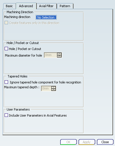
Click OK to start the feature recognition process.
- Optional: Click Cancel in the progress bar that appears to interrupt the process.
An information box appears giving a summary of the process:
All recognized machinable features are added to the Manufacturing View.
A typical design part is represented below:
![]()
Create All Prismatic Machinabe Features from the Technological Results
You can create Prismatic Machinabe Features from the Technological Results. The Create Axial Features from Tech. Results is supported for both Global Feature Recognition by Body and Face. It is not supported for machinable axial feature creation by Local Feature Recognition. All the Hole features are read from the list of Technological Results, and the corresponding Prismatic Machinabe Features are created.
Select Create Axial Features from Tech. Results check box in Global Feature Recognition dialog box to create machinable axial features from the technological results.
Only the relevant parameters remain active and the Global Feature Recognition dialog box turns into:
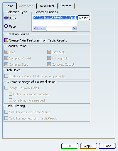
The selection of this check box helps to recognize holes from the technological results. The moment you select Create Axial Features from Tech. Results check box, the following functionalities in the Global Feature Recognition dialog box become disabled:
- The entire Feature frame is disabled as the recognition type is applicable for holes only.
- Tab Holes and Automatic Merge of Co-Axial Holes checkboxes are disabled as hole creation is governed by technological results.
- Hole Filtering checkboxes are disabled.
- The entire Advanced tab is disabled as creation of feature and parameter are governed by technological results.
Note: Machinable axial features created throughthe technological results can be updated for changes in technological results by selecting the Create Axial Features from Tech. Results check box and running feature recognition process again. The existing machinable axial feature are updated with the new parameters, if any. But if there is some changes in the design; the geometry of the hole is changed by adding, removing, or modifying faces, these holes are considered as new ones, and the old machinable axial features are not updated with the new parameters.