Creating a Machining Pattern on Machinable Features | ||||||
|
| |||||
Click Pattern Creation
 in the Axial Machining Operations toolbar.
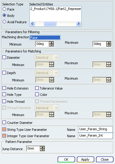
The Pattern Creation dialog box appears.
Set Selection Type to Body then select the part in the authoring window.
The pattern creation takes the associated Body object into account.

Specify the parameters for filtering:
- Click the Machining direction
field, then select a geometric element in the authoring window to specify the
machining direction (for example, selecting a face as
shown means that the machining direction can be taken
perpendicular to that face).
Only those axial machinable features in the specified machining direction can be taken into account for the pattern.
- Specify the Minimum and Maximum deviation angles corresponding to the selected Machining direction.
- Click the Machining direction
field, then select a geometric element in the authoring window to specify the
machining direction (for example, selecting a face as
shown means that the machining direction can be taken
perpendicular to that face).
Specify the parameters for matching:
- Select the Diameter and Depth checkboxes and then select Identical or Range.
The Minimum and Maximum deviation angles fields become enabled after selecting Range.
- Specify the Minimum and Maximum deviation angles corresponding to the selected Machining direction.
- Select the Hole Extension check box to create hole patterns by matching hole extension.
- Select the Hole Type check box to create hole patterns by matching hole type.
- Select the Tolerance Value check box to create hole patterns by matching tolerance value.
- Select the Color check box to create hole patterns by matching color of holes.
- Select the Hole Thread check box to create hole patterns by matching hole thread and thread parameters.
- Select the Counter Diameter check box to create hole patterns by matching counter diameter value.
- Select String Type User Parameter and Integer Type User Parameter checkboxes and specify user parameter names.
Selecting String Type User Parameter and Integer Type User Parameter checkboxes enables the corresponding text box for parameter name input. Enter the name of the user parameter that needs to be used for reading the parameter from axial features for Pattern creation. You can select a single parameter or both the parameters together and enter their names.
- Specify Jump Distance as pattern parameter.
- Select the Diameter and Depth checkboxes and then select Identical or Range.
Click OK to create the machining pattern.
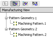
- Select Sort by Patterns in the Manufacturing View contextual command to check that the pattern is added to the Manufacturing View.

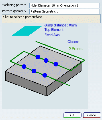
Double-click the Machining Pattern in Manufacturing View to display the Machining Pattern dialog box.

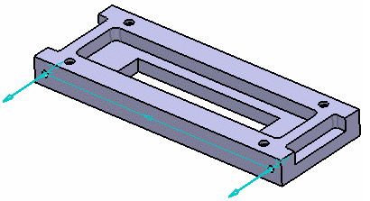
The pattern is visualized in the part:
