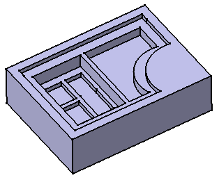
Click Multi-Pocket
 in the Sketch-Based Features toolbar (Pockets sub-toolbar).
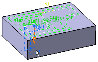
Select the sketch that contains the profiles to be extruded.
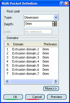
The Multi-Pocket Definition dialog box appears
and the profiles are highlighted in green. For each of them,
you can drag associated manipulators to define the extrusion
value.
The red arrow normal to the sketch indicates the proposed
extrusion direction. To reverse it, you just need to click it.
The Multi-Pocket Definition dialog box displays
the number of domains to be removed. In our example, the application
has detected six domains, as indicated in the Domains
section.
Select Extrusion domain.1 from the dialog
box.
Extrusion domain.1 now appears in blue in the geometry area.
Specify the length by entering a value. For example,
enter 10mm.
You need to repeat the operation for each extrusion
domain by entering the value of your choice. For example, select
Extrusion domain.2 and Extrusion domain.6 and
enter 30mm and 40mm respectively.
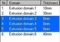
Note that you can multi-select extrusion domains from
the list before defining a common length: multi-select Extrusion
domain.3, Extrusion domain.4, and Extrusion domain.5,
then enter 50 as the common length value.
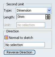
Click More>> to expand the dialog box.
In the Second Limit box, you can specify a length value for
the direction opposite to the direction previously defined.
Note that the Thickness section displays the sum of two lengths
defined for a given extrusion domain.
Click OK to create the multi-pocket.
The multi-pocket (identified as Multi-Pocket.xxx) is
added to the specification tree.
