Attach a Machining Operation to a Machining Feature
You can attach Machining Operations to machining features from the Manufacturing View
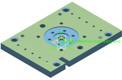
Open a part like this one.
- Select .
A PPR context with an empty Machining Cell is created. An empty Activities Process Tree opens automatically.
- Create a generic machine or assign a machine from the database.
As soon as a machine is assigned to the Machining Cell, a Part Operation and a Manufacturing Program are created in the Activities Process Tree.
- Alternatively, open an existing Machining Process or PPR context .
 By default,
the
Activities Process Tree opens
automatically.
- Click
 Axial Machining Operations.
- Click
 Global feature recognition in the Prismatic Machining Preparation Assistant sub-toolbar and select the part. Global feature recognition in the Prismatic Machining Preparation Assistant sub-toolbar and select the part.
- In the dialog box that appears, set the parameters as follows:
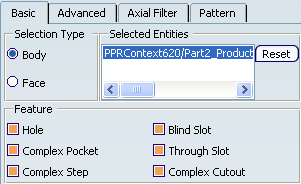

and click OK to validate and exit the dialog box.
Global feature recognition recognizes holes and creates pattern from these holes.
Click  Manufacturing View in the top left toolbar.
- If necessary, right-click the Manufacturing View header and select the requested item in the contextual menu:
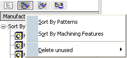
The machining features found are listed:
- With Sort By Features:
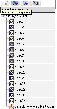
- with Sort By Patterns:

Still in the Axial Machining Operations toolbars:
- Click
 Spot Drilling in the Drilling Operations sub-toolbar. Spot Drilling in the Drilling Operations sub-toolbar.
- Select the Hole.5 in the Manufacturing View in the Sort by Machining Features view.
The Spot Drilling dialog box opens at the Geometry tab. Since you have already selected a hole, the sensitive icon shows 1 Point.
- Click 1 Point in the sensitive icon, and still in the Manufacturing View, select Hole.6, Hole.7 and Hole.8 that correspond to this machining pattern:
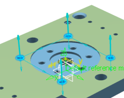
1 Point has turned to 4 Points
- Assign a tool to the Machining Operation and click OK to validate and exit the dialog box.
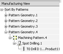
A new Pattern Geometry is created, visible in the Sort By Patterns view. The Machining Pattern created by the Spot Drilling and the Spot Drilling operation itself are attached to it.
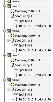
In the Sort by Machining Features view, the same elements are attached to the holes.
Click Drilling
 . .
-
In the Geometry tab of the Drilling dialog box, select the Machining Pattern.4 that you have created above, from the list.

The dialog box is updated with the geometry of this pattern.
-
Click OK to create the
Drilling operation.
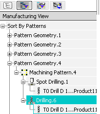
The Drilling operation is created under Machining Pattern.4, with the Spot Drilling operation.
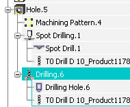
Select the
Manufacturing Program and click  Tool Path Replay to check that both Machining Operations use the same machining
pattern based on the initial feature selection. Tool Path Replay to check that both Machining Operations use the same machining
pattern based on the initial feature selection.
Note:
If you edit the Machining Pattern.4
(to include more points, for example) both the Spot
Drilling and Drilling operations will be updated.

Create an Axial Machining Operation on a Machinable Feature
You can create an Axial Machining operation on a Machinable Feature.

Create an Axial Machining Operation on a Hole under a Machinable Feature
You can create an Axial Machining operation on a Hole under a Machinable Feature.
-
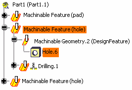
Select a hole under a Machinable Feature (e.g. Hole.6 under MachinableFeature (hole)) and create the Machining Operation (e.g. Drilling.1).
The behavior is the same as if you had selected the hole directly. If the hole is patterned, a Machining Pattern with several positions
is created, with the new Machining Operation below that
pattern.
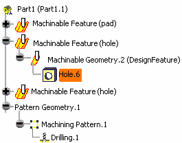
If the hole is not patterned, the machining feature represents that
hole and the Machining Operation appears below both the machining feature and the
pattern.
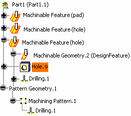
|
![]()
![]()


