Maximum Turning Envelope | ||||
|
| |||
From the product containing the part to machine:
- Select Start > Machining > Machine Programming.
A PPR context with an empty Machining Cell is created. An empty Activities Process Tree opens automatically.
- Create a generic machine or assign a machine from the database.
As soon as a machine is assigned to the Machining Cell, a Part Operation and a Manufacturing Program are created in the Activities Process Tree.
- Alternatively, open an existing Machining Process or PPR context .
 By default,
the
Activities Process Tree opens
automatically.
- Select Start > Machining > Machine Programming.
Click
 Utilities.
Click
 Maximum Turning Envelope in the Geometry Creation sub-toolbar.
You can compute the Turning profile of a part.
The Maximum Turning Envelope dialog box appears.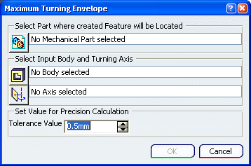
Define where you want to create the Maximum Turning Envelope.
Define the geometry:
- Click
 Input Body, then select
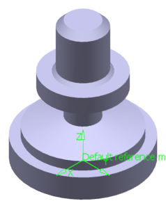
a PartBody containing the geometry you want to work on.
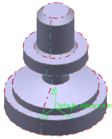
This is also the geometry selected as Design Part in the Part Operation. See Creating a Part Operation.
- Click
 Turning axis, and select the desired turning axis from the part selected in step 3.
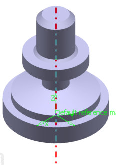
- The turning axis should be the axis of the machine assigned to the Part Operation.
- The turning axis may be initialized with the main spindle axis. So this step becomes optional.
- Click
Click OK
Two features are created under the part selected as the Mechanical Part:
- A solid, named Maximum Turning Envelope Feature.1_Solid:
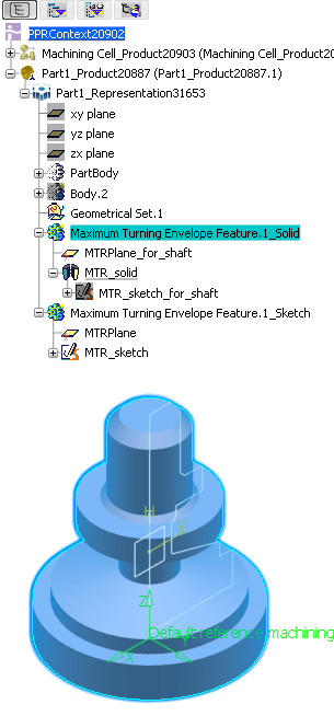
- a sketch named Maximum Turning Envelope Feature.1_Sketch that can be selected as geometry for Machining Operations.
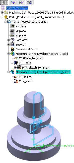
- A Maximum turn envelope machinable feature is created in the
Manufacturing View.
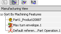
It has a contextual menu: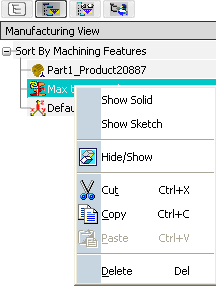
Note: If you delete the machinable feature, you will have to manage existing Machining Operations linked to it.
In addition to this contextual menu, you can double-click Maximum turn envelope to open the dialog box and edit it (modify the input, modify the Tolerance Value). - When an update is required, edit the machinable feature and recompute it.
- A solid, named Maximum Turning Envelope Feature.1_Solid: