Selecting Faces to Define Geometry | ||||||
|
| |||||
In the dialog box of a Machining Operation, right-click the geometry for which you need to select faces.
Note:
- Any hidden geometry selected using these commands is not taken into account in subsequent tool path computations. For more information, refer to the rules described in Influence of the Hide/Show Status of Selected Elements.
- Regarding the selection of faces in a Body: Each face of a Body is linked to the container which is immediately above it in the specification tree. This container is either a PartBody or a Geometrical Set. It is highlighted in the specification tree when you pass the cursor over the face. This can be important when a face linked to a body is selected in a Machining Operation. It is the container that is taken into account for machining and toolpath computation.
The Face Selection dialog box and the Tool Palette appear. See About Face Selection.
- Select two adjacent faces (to give the direction of selection).
- Click Navigate on Belt of Faces

All the faces that are adjacent to the one you have selected are selected.
To select a belt of faces up to a face:
- Select two adjacent faces (to give the direction of selection),
- Click Navigate on Faces Until a Face

- Select a third face where you want to end your selection.
All the faces between the start and stop faces that are adjacent are selected.
Select a face and click Navigate on Faces
 to navigate on faces
All the faces tangent to the one you have selected are selected.
The contour of the selected faces is highlighted.
To select faces within a polygon trap:
- Click Faces in a Polygon Trap
 .
. - Pick in the authoring window to draw a polygon around the faces to be selected.
- Double-click to end the selection.
All the faces that are situated entirely within the polygon are selected
- Click Faces in a Polygon Trap
Select a face of a given color and click Retrieve Faces of Same Color
 .
.All the faces with the same color as the one you picked are selected.
In Multi-Axis Flank Contouring operations, click Multi-selection of Face
 to select a face more than once while defining the drive element.
To select faces belonging to previously created selection set:
- Click Selection Sets
 .
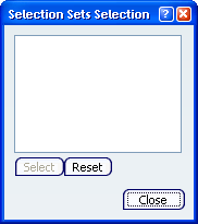
.The Selection Sets Selection dialog box is displayed.

- Proceed as explained in Selection Sets.
- Click Selection Sets
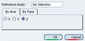
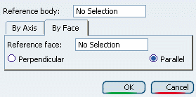
The Define Normal Faces dialog box appears to let you select faces from a Reference body that are:
- normal to a main axis.

- or parallel or perpendicular to a
face that you select as reference.

- normal to a main axis.
Use the Tools Patette to multi-select face elements.

- Select
 to select or deselect elements in the authoring window.
 - Selection Trap
 to draw a trap and select the elements entirely located inside this trap.
 - Intersecting Trap
 to draw a trap to select elements that are either located inside the trap or intersected
by the trap.
 - Polygon Trap
 to draw a polygon to select any element inside this polygon.
 - Paint Stroke Trap to select elements by drawing a paint stroke across them.

- Outside Trap Selection
 to draw a trap to select the elements strictly located outside the trap.
 - Intersecting Outside Trap Selection
 to draw a trap to select elements that are either strictly or partially located outside the trap.
- Select
Click Reset All Selections
 to resets all the current selections.
When you are done:
- Click OK to validate and exit the Face Selection dialog box.
- Click Cancel to exit the Face Selection dialog box without selecting faces.