About TRACUT Operator Instruction, COPY Operator Instruction and Copy-Transformation Instructions | |||||
|
| ||||
Differences between TRACUT Operator Instruction, COPY Operator Instruction and Copy-Transformation Instructions
This information helps you select the operator you require.
The essential differences are as follows:
- A TRACUT Operator Instruction is used to apply a transformation to a delimited sequence of activities in the Manufacturing Program, to machine a symmetrical part. The sequence is delimited by TRACUT-TRACUT/NOMORE type instructions.
- A COPY Operator Instruction is used to copy and apply a
transformation to a delimited sequence of activities in the
Manufacturing Program.
The sequence is delimited by COPY-INDEX type instructions.
To compute the COPY Operator Instruction, all the referenced operations must:
- be up-to-date or locked,
- have a tool path.
- A Copy-Transformation Instruction is used to copy and
apply a transformation to a selected list of operations with the same tooling (not a
delimited sequence).
A Copy-Transformation Instruction allows you to order those Machining Operations, while a COPY Operation Instruction does not. To compute the Copy-Transformation Instruction, all the referenced operations
must:
- have the same tooling,
- be up-to-date or locked,
- have a tool path.
In addition:
- A TRACUT Operator Instruction and a COPY Operator Instruction are very similar to their counterparts in APT NC language.
- Tool path edition is not possible with a TRACUT Operator Instruction or a COPY Operator Instruction.
- TRACUT Operator Instructions are not taken account in the computation of Intermediate Stock.
![]()
Transformation Types
The transformations are defined the same way in the three commands.
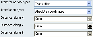
- Translation
- Defined by the Translation type and distances:
- Absolute coordinates: the Distance along X, Distance along Y and Distance along Z are given in the absolute machining axis system.
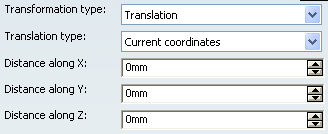
- Current coordinates: the Distance along X, Distance along Y and Distance along Z are given in the current machining axis system.
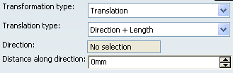
- Direction + Length: the Direction is given by a linear geometric element, the length is given as a Distance along direction.
- Absolute coordinates: the Distance along X, Distance along Y and Distance along Z are given in the absolute machining axis system.
- Rotation
- Defined by:
- a Single axis i.e. a linear geometric element selected in the authoring window, and a rotation Angle,
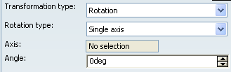
- or the Machining axis, and a rotation Angle,
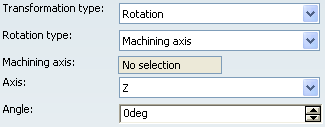
Note: If a circular edge is selected, the normal axis of the circle is used.
- a Single axis i.e. a linear geometric element selected in the authoring window, and a rotation Angle,
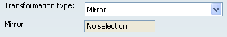
- Mirror
- Defined by a planar geometric element used as the axis of symmetry.
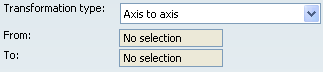
- Axis to axis
- Defined by a transformation From a first machining axis system To another machining axis system that you select in the authoring window. The first axis system is transformed into the second axis
system.
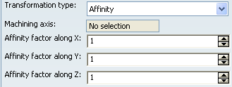
- Affinity
- Defined by a Machining axis system and the Affinity factor along X, Affinity factor along Y, Affinity factor along Z. The transformation
matrix in the selected machining axis system is:
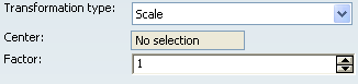
- Scale
- Defined by a planar surface or a point as the Center, and a Factor applied along the normal projection on the selected element.
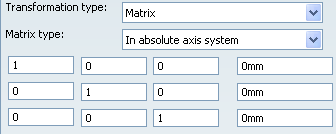
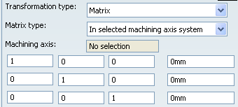
- Matrix
- Defined by the matrix
definition of the transformation in an axis system:
- In absolute axis system,
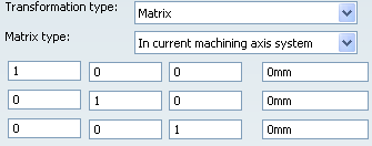
- In current machining axis system,
- In selected machining axis system,
Note:
- When the matrix is defined in the absolute axis system or in the current machining axis system, the matrix of the transformation is stored in the model in the absolute axis system (it is invariant in this axis system). Choosing one or the other mode only changes the display of the coordinates of the matrix.
- Out of a current machining axis system context, the absolute axis system can be used to display the matrix.
- When the matrix is defined in a selected machining axis system, the matrix of the transformation is stored relatively to this selected machining axis system.
- In absolute axis system,
![]()
Status of the Operators in the Activities Process Tree
A symbol is added to the operator icon when information is missing  or not up-to-date
  .
.
TRACUT Operator Instruction
A TRACUT Operator Instruction has a Missing Information status when:
- some reference geometry has been deleted.
A TRACUT Operator Instruction has a Not Up to Date status when:
- some reference geometry has been modified
- a parameter has been modified.
COPY Operator Instruction
A COPY Operator Instruction has a Missing Information status when:
- some reference geometry has been deleted
- INDEX and INDEX/NOMORE are inconsistent.
A COPY Operator Instruction has a Not Up to Date status when:
- some reference geometry has been modified
- a parameter has been modified.
Copy-Transformation
A Copy-Transformation has a Missing Information status when:
- some reference geometry has been deleted
- all referenced operations have been deleted.
A Copy-Transformation has a Not Up to Date status when:
- some reference geometry has been modified
- a referenced operation has been modified or deleted
- a parameter has been modified.
![]()
NC Data Output Considerations for Copy-Transformation
A Copy-Transformation Instruction allows you to produce NC data that takes into account the specificities of the selected Machining Operations (CYCLE syntax or GOTO statements, Compensation, Profile, Tip/Axis, Contact/Norm, PQR, and so on).
During NC data generation, the tool path of the Copy-Transformation Instruction of
an ordered list of Machining Operations can, for each of its sub-paths
corresponding to a specific Machining Operation, read the complementary
information on this Machining Operation to associate to the particular treatment
of this sub-path:
- If the CYCLE syntax is ON in a selected machining operation, the sub-path can be output is this mode.
- The tolerance and discretization step of the selected machining operation are taken into account to process double points for this sub-path.
- If profile data exists on an operation, the sub-path can be output in this mode.
- Compensation data can be read for this sub-path on the selected Machining Operation.
The Copy-Transformation Instruction output takes into account data available in the tool path and in the selected Machining Operations.
If a Copy-Transformation Instruction references various Machining Operations with specific data that differs from one Machining Operation to another, each sub-path of the Copy-Transformation Instruction can be processed individually.
Machining Operations using CYCLE syntaxes and GOTO statements can be mixed in a Copy-Transformation Instruction: the output can be composed of CYCLE syntaxes and GOTO statements.
Deactivated Machining Operations are taken into account for the computation of a Copy-Transformation Instruction.