Go to and select the display color of the Spindle Rotation Arrow and of the Spindle Rotation Arrow Head from the lists.
Insert a Rough Turning operation in the Activities Process Tree and compute the tool path.
See Creating a Rough Turning Operation
Place the pointer over the Rough Turning operation in the Activities Process Tree.
Information about spindle number, spindle name and its direction of rotation is displayed as tooltip.
Click Synchronization Wizard  in the NC Control toolbar to start the synchronization.
See Creating and Editing Synchronization
Place the pointer over the Rough Turning operation in the synchronization view that appears.
Information about spindle number, spindle name, and its direction of rotation is displayed as tooltip.
Right-click the spindle in PPR Context and select .
The spindle direction is displayed as a 3D arrow in the authoring window.
 By default,
- arrow is positioned on the plane perpendicular to the
spindle axis.
- diameter of the arrow is determined by
the maximum size of the product to machine.
Use the mouse to manipulate the
spindle arrow diameter and position.
- Use left mouse
button to change the radial position of the arrow.
- Use the left and middle mouse buttons to change the axial position of the arrow.
- Double click in the authoring window, to store the diameter and position
of the arrow for the spindle.
The stored diameter and position can be used for simulation.
Select Rough Turning operation and Drilling operation having fixed
tool and click Tool Path Replay  .
.
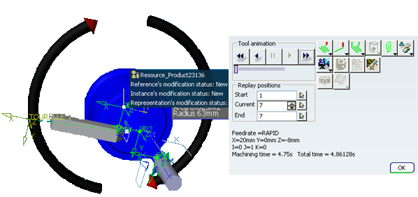
Spindle rotation is shown for Lathe operation and Axial operation with fixed tool. The below image shows spindle way of rotation during Tool Path Replay.

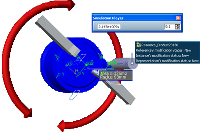
If a spindle is involved simultaneously in more than one activity with different ways of rotations, the spindle arrow is displayed in red color with two arrow heads indicating both clockwise and
counterclock wise directions as shown in the image below (Time-based replay).

Note:
Spindle direction display is not supported during Time Based Video simulation.