B-Axis Management and Tool Axis Flip | |||||
|
| ||||
B-Axis Management
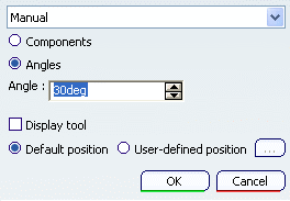
A Tool Axis symbol on the turning operation's Strategy tab allows the B-axis orientation to be set and eliminates the need for a tool change activity.
Tool Axis for Turning Operation
Tool axis is defined on turning operations linked to a mill turret (managing a B-axis). Information that B-axis is managed on turret is defined on the machine.
Turret type can be defined as Mill Turret on the NC machine.
No tool axis can be defined on turning operations which gave rotary turret defined. Tool axis can be defined according to the spindle axis system.
Note: For multi-spindle machine:
A spindle axis system is defined on each spindle. Tool axis is defined on the main spindle axis.
For all Machining Operations affected to the counter spindle, the tool path computation is always done according to the main spindle axis system. If capability to compute coordinates in the counter spindle is provided, the tool axis of Machining Operation affected to the counter spindle can be defined in the counter spindle axis system.
Tool axis is defined by geometry selection or manually (by component values or angle value). Angle orientation is defined from the radial axis to the axial axis of the spindle axis system. See Defining the Tool Axis
Tool Path Replay
For turning operation defined on a mill turret (on which B-axis is defined),
the tool is displayed according to the orientation defined by the tool axis.
The tool axis specified by you can be displayed on the Tool Path Replay
dialog box and is generated in the APT output.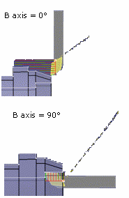
For turning operation defined on another turret (not a mill turret), the tool axis is vector normal to the turning plane.
Output File Generation
BAXIS NC command is output at the beginning of Machining Operation defined on a mill turret.
	$$ OPERATION NAME : Rough Turning.1
	$$ Start generation of : Rough Turning.1
	$$
	FEDRAT/ 0.3000,IPR
	SPINDL/ 70.0000,RPM,CCLW
	BAXIS/1.000000, 0.000000, 0.000000
	GOTO / 58.63072, 0.00000, 136.34210
	GOTO / 58.63072, 0.00000, 134.34210
	FEDRAT/ 0.4000,IPR
	GOTO / 58.63072, 0.00000, 81.85882
	FEDRAT/ 0.8000,IPR
	GOTO / 58.84286, 0.00000, 82.07095
This syntax contains valuation of I, J, K coordinates of the operation tool axis (defining the B-axis orientation). Coordinates are defined in the machining axis (spindle axis). For example: BAXIS/1,0,0.
Turret axis orientation components (I, J, K) are generated in the output file (according to the options set in Tool Motions in the NC Output tab of Machine Editor dialog box).
TLAXIS syntax (that is output for a machine axis change) is not modified: coordinates of TLAXIS statement are the components of the vector normal to the turning plane.
For the following statement the output depends on the options set in Tool Motions:
- GOTO statement
- TLAXIS (output for machine axis change)
- BAXIS to indicate B-axis orientation.
Operation Defined on a Mill Turret
NC data format statement = (X,Y,Z):
X, Y, Z
BAXIS/I,J,K
TLAXIS/Inormal, Jnormal, Knormal (components of the normal to the turning plane)
NC data format statement = (X,Y,Z,I,J,K):
X, Y, Z, I, J, K
Operation Defined on Another Turret
NC data format statementt = (X,Y,Z):
X, Y, Z
TLAXIS/Inormal, Jnormal, Knormal (components of the normal to the turning plane)
NC data format statement = (X,Y,Z,I,J,K):
X,Y, Z,Inormal, Jnormal, Knormal
Inormal, Jnormal, Knormal are the components of the axis vector normal to the turning plane. I, J, K are the components of the tool axis orientation vector that define the B-axis position.
Note: TLAXIS cannot be output in the APT file for a turning operation, unless an explicit Machine Axis Change is added. An exception to this is when there is a change from milling operation to a turning operation. In this case, TLAXIS/ Inormal, Jnormal, Knormal can be output before the turning operation.
Machine Simulation
B-axis move is simulated according to the tool axis defined on the turning operation.
APT Source File Import
Import of APT source file on which I, J, K coordinates are defined; tool axis is defined with the I,J, K coordinates.
At replay and simulation, if tool axis is not correct (not in the turning plane) then radial axis is used for tool assembly orientation.
BAXIS syntax can be correctly interpreted by APT import functionality
only when the syntax is defined with a known order of parameters (the required
parameters of the syntax must respect the default syntax).
Tool path can be correctly replayed only when:
- All the required parameters are set
- The parameters are set in the specified order.
Major word and parameters must be set as follows:
BAXIS,/%MFG_MILL_TURRET_I_AXIS, %MFG_MILL_TURRET_J_AXIS,
         MFG_MILL_TURRET_K_AXIS
Change in Machining Operation Status
If you change the turret assigned to a machining program from one turret type to another type. ie. from Rotary to Mill Turret or vice versa. The Machining Operation status becomes Not up to date.
If you cut, copy, and paste a Machining Operation related to one turret type to another turret type (for example, from Rotary Turret to Mill Turret or inversely), the Machining Operation can have status Not up to date.
![]()
Tool Axis Flip
Observe change in tool path behavior through Tool Axis Flip.
The Tool Axis Flip check box on the turning operation's
Strategy tab
![]() provides a tool rotation (0/180 degrees).
provides a tool rotation (0/180 degrees).
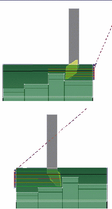
This allows machining of different areas (front and back areas of a part, or part on main spindle and part on a counter-spindle) using the same tool assembly. Only the tool orientation (inversion) differs when machining the different areas or parts.
NC_MILL_TURRET_INVERSION NC command is output at the beginning of operation defined on a mill turret:
$$ TOOLCHANGEEND
$$ End of generation of : Turning Tool Change.1
$$ OPERATION NAME : Rough Turning.1
$$ Start generation of : Rough Turning.1
CAXISINVERTED/1
SWITCH/9
FEDRAT/ 0.3000,MMPR
SPINDL/ 70.0000,RPM,CLW
BAXIS/ 1.000000, 0.000000, 0.000000
GOTO / 45.62158, 0.00000, 275.61398
NC_MILL_TURRET_INVERSION is defined as :
*START_NC_COMMAND NC_MILL_TURRET_INVERSION
*START_SEQUENCE
CAXISINVERTED/%MFG_MILL_TURRET_AXIS_INVERT
*END
*END
%MFG_MILL_TURRET_AXIS_INVERT: the value of this parameter indicates whether the mill turret is at inverted position or not.
Possible values:
- 0: not inverted (C axis = 0°)
- 1: inverted (C axis =180°)