Replace a Reference Element Using the Definition Command
You can replace a reference element in
associative use-edges using the Definition command.
If necessary, double-click the front
view to activate it.
In the view, select the use-edge for
which you want to replace the input geometry.
Right-click this use-edge to display
the contextual menu, and select Definition to edit the reference
element. You can also double-click this use-edge.
The 2D Layout
Use-Edge Edition dialog box is displayed. In the geometry, select another element
to be used as input for the use-edge.
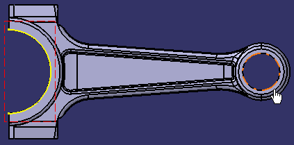
Click OK.
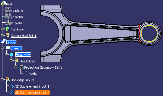
The use-edge geometrical
input is modified. 3D Sub-element input.2 is added to the
specification tree under the Use-edge input node.

Replace a Reference Element Using the Replace Reference Geometry Command
You can replace a reference element in
associative use-edges using the Replace Reference Geometry command.
If necessary, double-click the front
view to activate it.
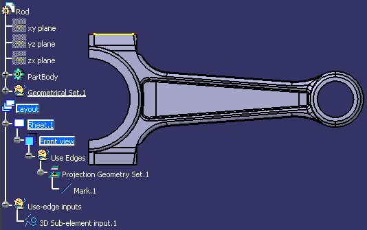
In the specification tree, select the
use-edge for which you want to replace the input geometry.
Right-click 3D Sub-element input.1
from the specification tree, and select 3D Sub-element input.1
object > Replace Reference Geometry.
In the geometry, select another element
to be used as input for the use-edge.
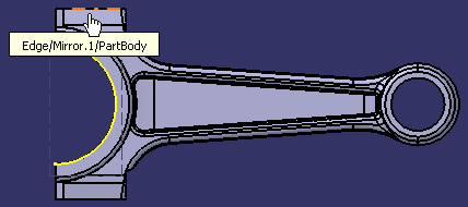
You can now notice that all use-edges created from this input, as
well as the layout, sheets and views containing these use-edges, turn
not up-to-date. You need to update the layout so that all changes on
the use-edge inputs are taken into account.
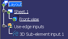
Click Update. You can notice
that the input geometry has been replaced.
|
![]()


