More about View from 3D | ||||
|
| |||
View from 3D
You can generate the following types of view from 3D:
- Projection views, section views, section cuts,
- Aligned section views, aligned section cuts, offset section views, offset section cuts.
| Important: In the Drafting workbench, it is not possible to create clipping views from drawing views that have been generated from a 2D Layout for 3D Design view. |
For more information about view from 3D, refer to Views.
![]()
2D Components
The Note Object Attribute (NOA) from a 2D component is now extracted in views from 3D. However, some restrictions apply:
- Information regarding the documents used to create the ditto (drawing, parts, catalogs) will be lost.
- Hidden texts and URLs on flag notes and Note Object Attributes will be lost during extraction.
![]()
Annotations
- You can move or modify annotations in views from 3D. However, if the part is modified and you subsequently update the view, any modification applied to the annotations in the drawing is lost. We advise you perform modifications on the 3D part directly.
- 2D annotations can be added to views from 3D.
- Changing the color of 3D annotations to white will not impact the color of annotations in the drawing: they are automatically displayed using the black color (instead of white) so that they can be readable against a white background.
![]()
Associativity
- Views from 3D are not associative to the geometry of the 3D view. So, if you modify the geometry of a 3D view, the definition of the corresponding 2D view is not modified at the next update, even if the 3D view is associative to the geometry.
- Extracted annotations are not associative to the geometry.
![]()
Dimensions
Curvilinear dimensions and chamfer dimensions generated with a view from 3D cannot be manipulated and are seen as not up-to-date (using the color defined for Dimensions for which last update failed in the Elements' Analysis dialog box available through Tools > Options > Mechanical > Drafting > Display tab, Elements Analysis area, selecting the Activate element's analysis check box, and by clicking Configure...).
![]()
Functional Tolerancing and Annotation Display Ratio
In Functional Tolerancing and Annotation, you can define a ratio to reduce or emphasize the display of an annotation. When generated,
- For front views, section views and section cuts, the ratio of the 3D annotation view is reversed and applied to the view geometry in the generated 2D drafting view.
- For aligned section views/section cuts and offset section views/section cuts, the ratio of the first 3D annotation view is reversed and applied to all the generated 2D drafting views.
![]()
Hidden 3D Geometry
Only the elements visualized in 3D (i.e. in Show mode) at the time of extraction are extracted in the view from 3D. In other words, any element hidden in 3D does not appear in the view. So if you show this element in the 3D part, then update the view from 3D, this element is displayed.
![]()
Standard
The parent standard used in the drawing representation and in the 3D Part (annotations) must be the same. Otherwise, both the view and the annotations may not be generated.
![]()
View from 3D Axis and Section Cut Callout
In a view from 3D, the H and V axis of the view must correspond to X and Y axis of the sheet. For this reason, the choice of the view in which to add a section cut callout is limited. In particular, the profile of the section cut must be horizontal on the chosen view. In the case of extraction views, the first line of the profile (i.e. corresponding to the first compounding view) must be horizontal.
![]()
Generation of Drawings or Views from 3D Using Generative View Styles
You can generate a drawing view from a 2D Layout for 3D Design view which uses a generative view style. In this case, the generative view style is entirely managed in the 2D Layout for 3D Design view and layout.
- If the 2D Layout for 3D Design view is associated with the generative view style, then the generated view will also have the same generative view style. However, you cannot modify or delete the associated generative view style.
- Views extracted from a layout with embedded generative view styles turn to not-up-to-date in the following cases:
- When an embedded generative view style is synchronized with its corresponding XML file, it is added to the layout or removed from the layout.
- When a generative view style is applied to, or removed from, any view in the layout.
![]()
Generation of View Background Geometry and Annotations
You can generate a drawing view which displays the 2D layout elements (i.e. geometry and annotations) seen in the background of a 2D Layout for 3D Design view.
The following 2D elements seen in the background of a 2D layout view are generated, independently without setting any option and even if placed behind another 3D object:
- Geometry of other 2D layout views.
- Annotations of other 2D layout views as well as annotations of Functional Tolerancing & Annotation views.
- Dress-up.
These elements are generated with the following restrictions:
- The element has to belong to the layout assembly.
- In case of an annotation or geometry, its support plane has to be parallel to the 2D layout view plane, and the annotation or geometry should be readable (i.e. not seen from behind).
Note that a view background view text is generated even if the 2D Layout for 3D Design view contains its own view text.
| Important: View background geometry or annotations are not generated in the views created prior to V6R2011x. |
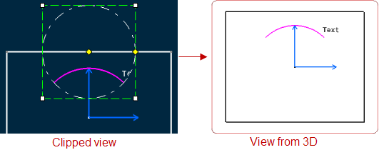
- Impact of Clipping Frame
The clipping frame set on a 2D Layout for 3D Design view is a visualization operator which clips the elements displayed in the background of the 2D Layout for 3D Design view.
It means the view background geometry is cut if it crosses the clipping area. As a consequence, the resultant drawing is generated with generative items trimmed on the clipping outlines.
However, the annotations and dress-up elements are not trimmed on the clipping outlines. They are generated if at least one representative point is present inside the clipping area. Else, they are not generated in the view background.
The following table provides the information of the representative points of all possible annotations and dress-up objects:
Type Objects Representative Point Annotations Balloon
Datum feature
Datum target
Dimension
Geometrical tolerance
Roughness symbol
Table
Text with leader
View text
Welding symbol
Text box corners Dress-up Center line
Axis line
Thread
Arrow
Area fill
Origin
Extremities
Origin
Extremities
Contour extremities
Other 2D component instance Origin