Creating Zones | ||||||
|
| |||||
Create a Logical Zone
This section describes how to create a Logical Zone component in the RFLP tree.
Click .
In the specification tree, the Logical Zone component is added.
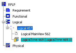
![]()
Create a Logical Zone with Shape
This section describes how to create a Logical Zone in the RFLP tree and a corresponding shape representation in the 3D area.
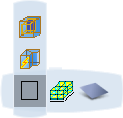
Click the arrow on the west quadrant of the Compass to open the toolbar.

In the toolbar select the type of shape you want to create:
-
 New Component with Box
 -
 New Component with Cylinder
 -
 New Component with Sphere
 -
 New Component with 3D Shape
A balloon appears in the 3D area. The type of balloon depends upon whether you chose a basic shape (Box, Cylinder or Sphere) or a detailed shape (3D Shape):
 or
or 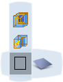
-
Optional: Basic shapes only (not 3D shapes): To define the dimensions of the basic shape, click
 and in the dialog box which appears enter the required values and then click Close.
In the balloon, select LogicalZone
 .
.Position the shape in the 3D area using one of the following placement modes:
- To position the shape on a surface or point, click Select Surface or Point
 and then select a surface, point or edge in the 3D area.
 - To position the shape by giving coordinates, click XYZ coordinate
 . In the dialog box which appears enter your coordinates and then click OK.
 - To position the shape anywhere in the 3D area, click Selection on Compass Plane
 (Robot plane) and then select a position in the 3D area.
When you have clicked to position the shape:
- In the 3D view, for basic shapes, the shape appears.
- In the 3D view, for 3D shapes, the shape axes appear.
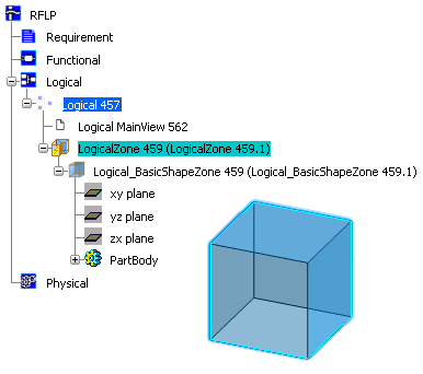
- In the specification tree, the Logical Zone component and associated Logical Shape representation (basic or detailed) are added.
Note: Nothing is added to the 2D view.
In this example, a basic box is created.
- To position the shape on a surface or point, click Select Surface or Point