Creating 3D Representation for Logical Components | ||
| ||
In the Logical tree, select the component you want to make a 3D representation for and click Create New 3D Logical Representation
 .
.The Logical 3D Representation / Logical 3D Representation Reference dialog box appears.
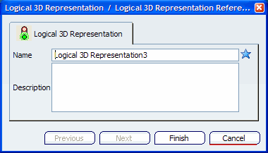
Type the Name and Description in the Logical 3D Representation / Logical 3D Representation Reference dialog box and click Finish.
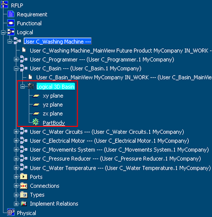
The newly created logical 3D representation is displayed in the tree under the selected logical component. You are now ready to create the 3D shape in one of the following workbenches:
-
Start
 > Systems > 3D For Logical Systems > Generative Shape Design
For Systems
> Systems > 3D For Logical Systems > Generative Shape Design
For Systems -
Start
> Systems > 3D For Logical Systems > Functional Modeling Part
For Systems
-
Start
> CATIA Live Shape
-
Start
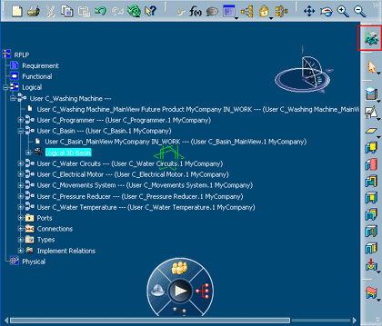
Double-click the newly created logical 3D representation in the Logical tree to activate the 3D shape edition workbench where you can create the 3D shape for the representation.
Note: Refer to the appropriate CATIA user guide for the workbench you are using to create a 3D shape.
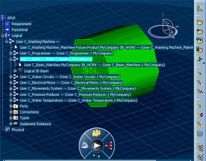
Once you are done creating 3D shape click on any logical component in the Logical tree of RFLP structure to return to the RFLP Editor window.
Your session is returned to the VPM Functional Logical Editor, and the newly created logical 3D representation is displayed.
To save your work, click Propagate
 in the Bar.
The Propagate dialog box appears.