Creating Implement Relations | ||||
|
| |||
Between Logical Components and Functions
When new logical components are introduced, implement links to function or requirement can be created to capture the reason why these components are added to the definition of the product. In this task we will make an implement relation between objects in the Functional and Logical trees in RFLP structure.
| Important: To create an implement relation between a sub-function and a logical sub-component, it is necessary to have their tree roots (their context) connected (by an implement connection). |
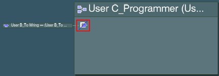
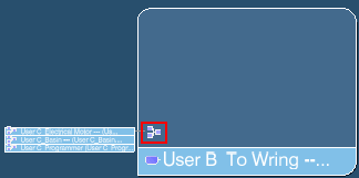
Select a logical component in the Logical tree and click Create an Implement Relation
 .
.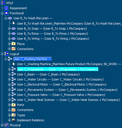
The Create an Implement Relation is highlighted. You can now select the function (function reference, function port, function connection) you want the logical component to be linked to.In the Functional category structure, select a function you want the logical component to be linked to. The Implement Relation dialog box appears.
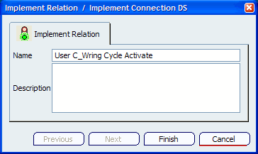
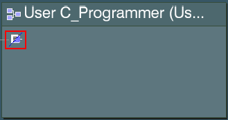
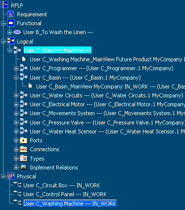
Type the name and description for the implement relation and click Finish. The implement relations have been created between the selected objects. The 2D representation of the logical component has an icon displayed, indicating that implement relation exists between logical component and a function.
Note: If implement relation is incomplete (one of the entity pointed by the relation is not loaded in session or has been deleted), the following is displayed in the Logical tree: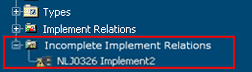
By default, incomplete implement relations are not visible. Select the Tools > Options > Infrastructure > VPM Functional Logical Editor > General tab to access options for Implement Relations Folders. Click the Display Incomplete Implement Relation Folder in tree check box to enable/disable the display of the incomplete implement relation folder in tree. Refer to the customization section for more information on settings for VPM Functional Logical Editor.- Click the icon in the 2D
representation to see the list of implemented/implementing
object to display.
- Click on an entry in the list to
display the main view the object (only if it is a function or a
logical component)
- Right-click the selected the 2D representation to see and use the contextual menu commands.
- Click the icon in the 2D
representation to see the list of implemented/implementing
object to display.
![]()
Between Logical and Physical Components
You can create implement relations for physical components.
When the new physical components are introduced, the implement links to logical component must be created to capture the fact that a given physical component implements the logical component of the product.
In this task we will make an implement relation between components of the Logical and Physical trees in RFLP structure.
Select a logical component in the Logical tree and click Create an Implement Relation
.
The Create an Implement Relation is highlighted. You can now select the physical component you want the logical component to be linked to.In the Physical category structure, select a physical component you want the logical component to be linked to. The Implement Relation dialog box appears.
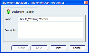
Type the name and description for the implement relation and click Finish. The implement relations have been created between the selected components. The 2D representation of the logical component has an icon displayed, indicating that implement relation exists between logical and physical components.
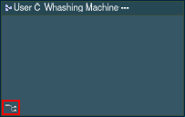
In the Physical category structure of the RFLP tree, like for the Functional and Logical categories, the created Implement Relation is displayed under the root of the tree structure of the selected physical component.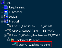
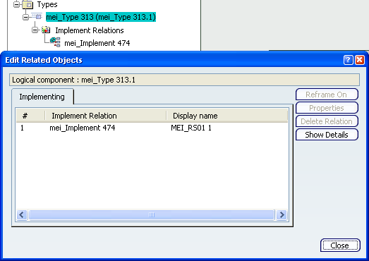
Use the Edit Implement Relations command to view the list of objects implemented by a physical
component.
command to view the list of objects implemented by a physical
component.
- Click the icon in the 2D representation to see the list of implemented/implementing object to display.
- Right-click the selected the 2D representation to see and use the contextual menu commands.
![]()
Between a Requirement and a Flow
When a new flow is introduced to answer a specific requirement, an implement relation can be created between them to capture this link. In this task we create an implement relation between a requirement and a flow in the RFLP structure.
You must have created:
- A requirement structure containing a requirement.
- A functional structure with ports and associated flows.
Select a requirement in the Requirement tree and click Create an Implement Relation
or right-click the requirement and select Create Implement Relation in the contextual menu.You can now select the flow you want the requirement to be linked to.
Type the name and description (optional) for the implement relation and click Finish.
The implement relation has been created between the selected components. The
 icon indicates that the implement relation exists between
the requirement and the flow.
icon indicates that the implement relation exists between
the requirement and the flow.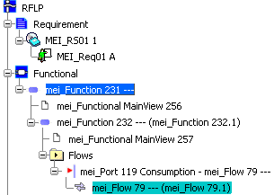
Note:
- The Edit Implement Relation command is available on Flows to see and edit the implement relation related to these objects.
- The Implement relations can be displayed in the Shading category of the PLM Compass East Quadrant when selecting the entities in the tree.
![]()
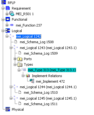
Between a Requirement and a System Type
When a new system type is introduced to answer a specific requirement, an implement relation can be created to capture this link. In this task we create an implement relation between a requirement and a system type in the RFLP structure.
You must have created:
- a requirement structure containing a requirement.
- a logical structure with ports with associated system types.
Select a requirement in the Requirement tree and click Create an Implement Relation
or right-click the requirement and select Create Implement Relation in the contextual menu.You can now select the system type you want the requirement to be linked to.
Type the name and description for the implement relation and click Finish.
The implement relation has been created between the selected components.
Note:
- The Edit Implement Relation command is available on types to see and edit the implement relation related to these objects.
- The Implement relations can be seen in the Shading category of the PLM Compass East Quadrant when selecting the entities in the tree.
- The Edit Implement Relation command is available on types to see and edit the implement relation related to these objects.
![]()
Between Flow and System Type
When a new system type is introduced to answer a specific flow, an implement relation can be created to capture this link. In this task we create an implement relation between a flow and a system type in the RFLP structure.
You must have created:
- a functional structure containing a flow.
- a logical structure with ports with associated systems types.
Select the system type you want the flow to be linked to and click Create an Implement Relation
or right-click the requirement and select Create Implement Relation in the contextual menu.