Adding a Pathway Connection Point | ||||||
|
| |||||
Select the surface, edge or point of a 3D Shape.
The Pathway Connection Point
 balloon appears.
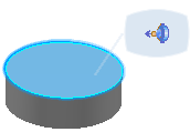
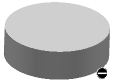
Click Pathway Connection Point
.Move the pointer in the 3D view to the selected shape.
- If it is not possible to add a pathway connection point on the shape, a black symbol is displayed. To overcome this, you should identify the shape as a detail type.
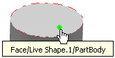
- If it is possible to add a pathway connection point on the shape, a hand symbol is displayed.
- If it is not possible to add a pathway connection point on the shape, a black symbol is displayed. To overcome this, you should identify the shape as a detail type.
Define the position of the new pathway connection point on the shape using one of the following methods:
- Click an empty position on a face.
- Click existing axis system on a face (marked by an X).
- Right-click to show the Add Pathway Connection Point dialog
box:
- Right-click the Location point box and create a point using one of the methods listed in the contextual menu, or select an existing point.
- Select a face to align the alignment vector
with the X-axis of the axis system.
 or
or 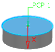
- Optional: Define a direction to orient the pathway connection point.
- Click OK when done.
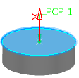
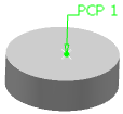
The pathway connection point is labeled on the shape.
The pathway connection point is created and published in the RFLP tree. An axis system is associated to the point.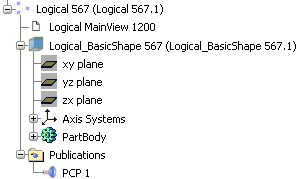
Note: To delete a pathway connection point, select the pathway connection point label on the shape. The pathway connection point is deleted, any links to logical ports are deleted, however the associated axis system and the X on the shape are not deleted.