Adding a Detailed Type to a Logical 3D Representation | ||
| ||
In the 2D View, select the logical component and click Create New 3D Logical Representation
 .
.Select the 3D Logical Representation.
The Detail Type balloon appears:
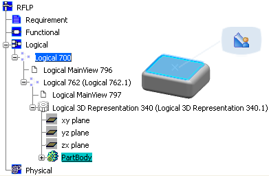
Select Detail Type
 to identify the 3D logical representation as a Detailed Shape type.
A Set Detail Type message appears: The Detail Type is set successfully. The 3D Logical Representation becomes a Detailed Shape:
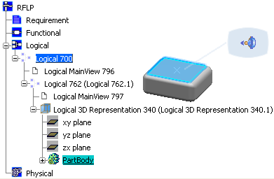
Note that the Pathway Connection Point balloon is displayed and the Logical 3D Representation icon has changed in the Specification Tree. If it is not the case, collapse the node and then expand it; by this way the icon of the Logical 3D Representation should be refreshed.
For more information about 3D logical representations, see VPM Functional Logical Editor User's Guide : Functional and Logical Definition : Logical : Creating 3D Representation for Logical Components