Associating a Pathway Connection Point to a Logical Port

This section describes how to associate a pathway connection point to a logical port.

Logical ports are used in the logical design to create logical relationships between logical components. Associating pathway connection points to logical ports is also used to define specific technological information, for example to link logical 2D routes to 3D pathways.

Note: You can associate a pathway connection point to more than one logical port, but you cannot associate a logical port to more than one pathway connection point.


Before you begin: Add a pathway connection point (PCP) to a shape.
Related Topics
Adding a Pathway Connection Point
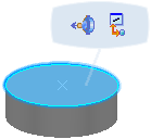
  1. Select the surface, edge or point of a 3D Shape containing at least one PCP.

    A balloon appears.

  2. Click Associate PCP Associate PCP.

    The Associate Ports dialog box appears.

  3. Optional: Click Show or Hide Association Ports Dialog to hide the dialog box.

  4. Select a logical component or an equipment center in the RFLP tree or in the 3D viewer.

    The name of the selected item is displayed in the dialog box. Pathway connection points are listed under Ports and displayed in the 3D viewer. Any available logical ports are listed.
    Associate Ports dialog box

    Note: Equipment center pathway connection points can only be associated to logical ports of equipment in the equipment center.

  5. Select a logical port from the Available list or an unhighlighted port in the Ports folder in the RFLP tree.

    The selected pathway connection point is associated with the selected port and the selected port appears in the Associated list.

  6. Click Close when done.

    You can see the PCP / Port association thanks to the cross-highlight between these elements.

Tips:
  • To remove the link between a pathway connection point and a logical port, select the logical port in the Associated list or a highlighted port in the Ports folder in the RFLP tree.
  • If you select an associated logical port in the RFLP tree or in the 2D view, the position of the pathway connection point to which it is associated will be highlighted by a blue arrow in the 3D view.