Inserting 2D Logical Components | ||||||
|
| |||||

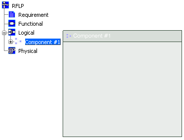
Insert a new logical component; in the RFLP tree, right-click Logical, select Insert New Reference and then in the Logical dialog box click Finish.
The logical component appears in the RFLP tree under Logical and a 2D representation of the component is displayed. In this example the component is named Component #1.
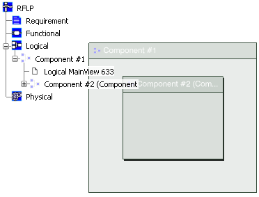
Right-click the 2D representation of the new component you have just inserted, select Insert New Reference and then in the Logical dialog box click Finish.
A new logical component appears in the RFLP tree under the component created in step 1 and a 2D representation of the component is displayed inside the first component. In this example the new component is named Component #2.
Repeat step 2 two more times, each time inserting a new logical component inside Component #2.
The two new components (#3 and #4) cannot be displayed inside Component #2. Instead a symbol
 indicates that additional components are present.
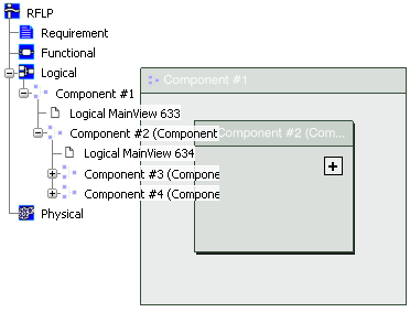
Click
to reveal the two additional components (if required, click  to hide them).
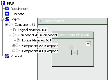
To learn how to manipulate the 2D representations of the logical components you have just inserted, follow the instructions given in VPM Functional Logical Editor Guide: 2D Graph and Tree Management.