Click Speed and Acceleration Probe .
.
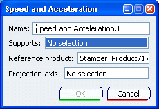
The Speed and Acceleration dialog box appears.

Select a point either in the specification tree or in the 3D viewer. The point is where the probe will be measured.
Specify a reference product.
The speed and acceleration values of the selected point are calculated with respect to a specific reference frame that is defined by this reference product.
Notes:
- By default, the main product is selected in the Reference product box. The reference product can be a moving product (relative values for the probe) or a fixed product (absolute values for the probe).
- If you define speed and acceleration probes for a kinematics scenario that references a submechanism, the values of the selected point are calculated with respect to the product that includes the submechanism. In this situation, the product to which belongs the submechanism is always specified as the reference product regardless the reference product that you selected primarily.
Optional:
Click the Projection axis box to activate it, and
specify the axis system in which the results are calculated.
Note:
By default, the main product axis system is selected in the Projection axis box.
Click OK.
The probe is identified in the specification tree under the Probes category. By default, the speed and acceleration probe is included in the current scenario. To include the probe in another scenario, edit the scenario of interest, and include the speed and acceleration probe. The speed and acceleration values are calculated during the computation of a scenario. See Simulating and Generating Results.
For each simulation step, values for the speeds (linear and angular) and accelerations are stored in the results and can be seen in the Kinematics Postprocessing workbench using the view scenario results capability.
