About Mechanism Representations | ||||
|
| |||
What is a Mechanism?
Mechanisms are defined as representations of a product that can be used to perform motion simulations.
Mechanism representations appear
under the product in the specification tree and are identified by
![]() .
.
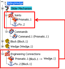
The engineering connections in a product form the basis of the joints in the mechanism representation; the configuration and motion of the mechanism is based on the degrees of freedom and relative motions allowed by the engineering connections. You can create a mechanism representation that uses only a subset of the engineering connections from the product. You can also create multiple mechanism representations for a single product, each using a different subset of engineering connections.

The relationship between engineering connections and mechanism representations is discussed in more detail in Creating Engineering Connections for Mechanisms.
![]()
What Does a Mechanism Contain?
A mechanism representation is defined by specific components including engineering connections, commands, and limits.
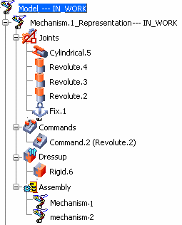
- Engineering connections: Define the relative motion between two parts. For example, a revolute connection implies that two parts can rotate about a common axis; however, they are not allowed to move in any other direction relative to each other. Engineering connections appear underneath the Joints node in the specification tree.
- Commands: Correspond to an unrestricted degree of freedom in an engineering connection that can be used to drive a simulation of the mechanism. For example, the unrestricted degree of freedom in a revolute connection is the relative rotation angle between the two parts; you simulate the motion of the mechanism by assigning various command values for this angle. Commands appear underneath the mechanism representation in the specification tree; the name of the engineering connection that a command drives appears in parentheses after the command name.
- Limits: Are upper and lower bounds for each command that
define the complete range of motion for an engineering connection.
For example, you can limit the relative angle in a revolute
connection to values between -90 and 180 degrees. Limits appear in
the Kinematics Simulation player when you run a
simulation.

- Dressup joints: Are multiple rigid engineering connections that fix together the components that belong to the model to the mechanism's components; they are created at once when using the Dressup function. Rigid engineering connections appear underneath the Dressup node in the specification tree as long as they connect a product in the mechanism to a product in the model. In other situations, they appear underneath the Joints node. For more information, see More about Dressup.
- Assembly: A collection of mechanisms that are assembled within a macro mechanism—also referred to as a multilevel mechanism. A mechanism can be both a macro mechanism or an assembled mechanism in different contexts. For more information, see More about Mechanism Assemblies.
For more information about creating and configuring mechanism representations, see Defining Mechanisms.