About the Mechanism Manager | ||||||||
|
| |||||||
To configure a mechanism, you can specify which engineering connections from the associated product are enforced in the mechanism to determine how the product components move with respect to each other. Enforced engineering connections appear under the Joints node in the mechanism representation.
The Mechanism Manager allows you to activate specific engineering connections in a mechanism, as well as define the commands that drive the mechanism. The Mechanism Manager also tracks the degrees of freedom (DOF) in a mechanism and indicates whether or not the mechanism can be simulated.
The Mechanism Manager dialog box comprises two tabs and an information area:
- The Joints tab that allows you to specify which joints are enforced in the mechanism.
- The Assembly tab that allows you to specifiy which mechanisms will be assembled.
- The Status area that gives the current DOF information, the number of commands, and specifies if interpendent commands exist for the mechanism. The color-coded status icon turns green when the mechanism can be simulated. The icons indicate the following situations:
| Status Icon | Meaning |
|---|---|
 |
The mechanism is fully defined and can be simulated. |
 |
The mechanism is partially defined and can be simulated.
|
 |
The mechanism cannot be simulated: no command is defined. |
The mechanism cannot be simulated: it is overconstrained. |
The Joints tab includes the following:
-
Joint List: Lists all available joints in the
mechanism. You can filter the list content by:
- Name of a joint or part of it using the Filter.
- Only included joints or All existing
joints in the mechanism.
Note: You can combine the Filter with Only included or All.
The Joint List table provides details for each
joint:
- Included: Indicates whether or not the joint is enforced in the mechanism. Joints can be included or excluded using the Joint Management buttons at the bottom of the dialog box.
- Name: Gives the name of the joint.
- Type: Gives the type of joint.
- Command 1/Command 2: For joints with controlled
constraints, indicates whether or not commands have been defined
for these variable DOF. The following messages are available:
- Length: A length-based command is assigned to the DOF.
- Angle: An angle-based command is assigned to the DOF.
- No: No command is assigned to the DOF.
- Not Drivable: A controlled constraint has not been created for this joint.
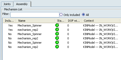
The Assembly tab includes the following:
- Mechanism List: Lists all available mechanisms below the parent product for the mechanism that is currently being set up. You can filter the list content. See the Joints tab for more information.
The Mechanism List table provides details for each
mechanism:
- Included: Indicates whether or not the mechanism is assembled. Mechanisms can be included or excluded using the buttons at the bottom of the dialog box.
- Name: Gives the name of the mechanism.
- Status: Displays the color-coded status icon for the mechanism.
- DOF with commands: Gives the current DOF information for the mechanism.
- Context: Provides the location of the mechanism within the product structure.