Click New View
 in the Views toolbar.
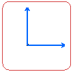
Click in the drawing to position the new view. An empty
view is created, displaying a blue axis in a red frame.

The drawing specification tree is updated to show the newly created view.
A specific icon is added to the specification tree.
Refer to
Drawing Specification Tree Icons for more information.

If you change your system's regional settings to use another language,
the default view name will be translated according to the language used
by your system (both in the view and in the specification tree). Of course,
this only applies to default view names; custom view names are not translated.
You can now create 2D geometry in this view.
Click the New View icon
 again and select a projection direction to create more views. The views
are created. As they are linked to the front view, they are projection
views.
The drawing specification tree is updated again to show the newly created
views.
Activate one of the projection views by double-clicking
it. For example, double-click the front view frame.
Click the New View icon
 to create the top view.
Note:
The view name and the view scale are displayed in the view as per the settings done by the administrator. For more information, refer to Managing View Texts.