Drawing Specification Tree Icons | ||
| ||
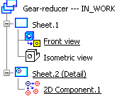
Tree Structure
The following picture represents a typical Drafting spcification tree.
Symbols

Important:
|
Generic Symbols
| Load/Open 3D Data Select Load 3D data or Open 3D data from the contextual menu to get an up-to-date status of links between the view and the 3D. Does not apply to interactive views. |
|
| Unreferenced drawing The drawing contains at least one sheet/view whose links with the 3D are broken. Does not apply to drawings which contain only interactive views. |
|
| Unreferenced sheet The sheet contains at least one view whose links with the 3D are broken. Does not apply to sheets which contain only interactive views. |
|
| Unreferenced view The link between the view and the 3D is broken. Does not apply to interactive views. |
|
 |
Current drawing |
| Design sheet | |
| Detail sheet | |
| 2D component |
Views
| Any type of Interactive Drafting view | |
| Front view | |
| Unfolded view | |
| Projection view | |
| Auxiliary view | |
| Isometric view |
Generative View Specifications
| Sections | |
|---|---|
| Aligned section cut | |
| Aligned section view | |
| Offset section cut | |
| Offset section view | |
| Detail Views | |
| Detail view | |
| Detail view profile | |
| Quick detail view | |
| Quick detail view profile | |
![]()
Masks Specific to Drafting Applications
Masks appear in the specification tree for different reasons. The following table illustrates these scenarios.
| Locked view Note that a locked view cannot be updated. Therefore, locked views which are not up-to-date will not be applied the corresponding mask. |
|
| Update error This mask appears in either of the following circumstances:
|
|
| View from View created from 2D Layout for 3D Design or from Functional Tolerancing and Annotations. |