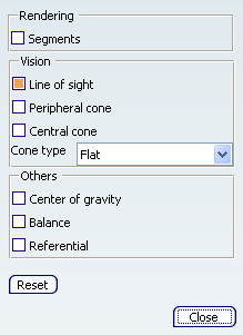
Display Dialog Box | ||
| ||
![]()
Vision
- Field of View
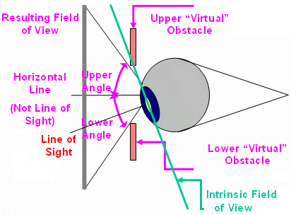
The field of view is the limit of what can be seen by the manikin. This zone is delimited vertically and horizontally by motionless obstacles around the eyes; eyebrows, cheeks and nose.
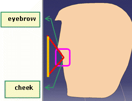
When somebody is looking down, the resulting field of view (visual field) orientation remains the same because the obstacles around the eyes don't move with the eyes. This is true until the eyes arrive at the limit of the eye "intrinsic field of view". But, this scenario is not taken into account in the vision model.
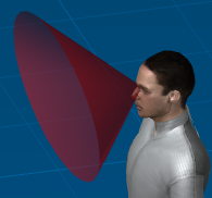
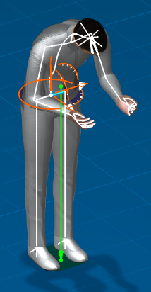
The vision cone is an arbitrary limit that can be specified in order to analyze what can be seen by the manikin inside a certain degree around the line of sight. This limit can represent an optical characteristic of the eye, like the limit for maximum acuity (approximately 1 degree) or the limit for colors discrimination (around 35 degrees). Previously, with this new vision paradigm is that the circle representing the central cone always kept the same shape no matter its position in the vision window (3D window) whereas all the objects at the periphery of the viewer was naturally deformed. To solve this problem, there is a 3D circle in the surface of the Visual Cone.
The display of the central spot is fixed at 3 degrees. It represents only the target of the line of sight.
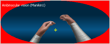
The central spot which corresponds to the line of sight (see The Vision Window Dialog Box) moves inside the vision window following the eyes motion. With this vision model, it is very important to make a clear distinction between field of view and Vision Cone (Using The Manikin's Visual Cone).
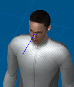
Line of Sight
Peripheral cone
Central cone

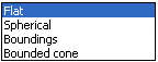
In the drop-down menu, the default type is Flat.
Choose from:
![]()
Others
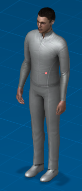
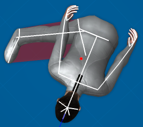
- Center of gravity
The center of gravity cannot be manipulated. However, the COG is constantly updated as the manikin's posture changes.
- Balance
The balance of the manikin is defined by a projection of the Center of Gravity (COG) on the support polygon of the manikin. The manikin is in balance if the point's projection is inside the polygon.
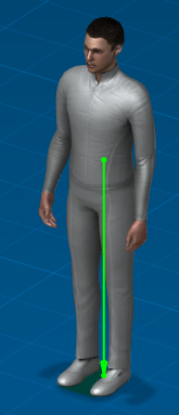
You can display the support polygon of manikin's balance in the viewer. The color of the support polygon changes from green to red if the manikin loses his balance.
You see the transparent support polygon of the manikin when the COG in the display is checked. If the manikin is out of balance, the polygon becomes red instead of green. The shape of the support polygon changes according to the change of posture of the manikin's lower body. The following pictures represent the case where the manikin' is in balance (COG project inside support polygon) and when he is not (COG projection outside support polygon).
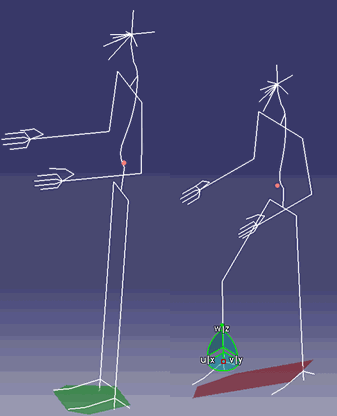
The support polygon is defined as the convex polygon of the outside portion of two feet.
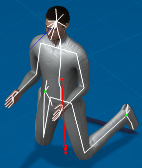
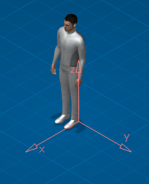
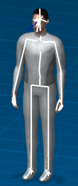
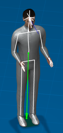
- Referential
- This shows the referential of the manikin.