Measuring Inertia

You can measure the 3D inertia properties (i.e. the area, density, mass, surface and volume) of a representation.

Inertia measurements are always non-persistent in VPM Digital Review and VPM Digital Validation, whereas they are persistent in Part Design.

This task shows you how to:


Before you begin: If the representation containing the inertia properties you wish to measure has no material applied, or if no density is applied to the material, then a default density of 1000kg/m3 is used.
Related Topics
About Notations Used for Inertia Matrices

Measure 3D Inertia

You can measure 3D inertia.

  1. Open the product or 3D shape representation on which you wish to perform your inertia measuring operation.

  2. To measure the inertia of a product, select Measure Inertia in the Review Creation toolbar or in the Measure Tools toolbar.

    Several things now happen:

    • The arrow pointer changes to the measure inertia pointer on the representations of the geometry or specification tree that can be selected for inertia measurement.

    • The Measure Inertia dialog box appears with the Specifications tab activated and all others grayed out. The Density field is automatically filled in (the value can be edited if it is the default density).

    Note: Inertia measurement is persistent in a 3D shape representation context. It is linked with the geometry, but not with the material.

  3. Using the measure inertia pointer , select a representation on which you wish to perform your inertia measuring operation, either in the specification tree or in the geometry.

    Tip: You can make a selection before launching the Measure Inertia command if you prefer. The Measure Inertia dialog box then appears with the corresponding information (and not grayed out as shown above).

    The representation name is shown in the selection field and the Customize, Results and Inertia/G tabs are activated by default. The Create Geometry, OK and Cancel buttons are also activated.

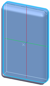
    In the geometry of the selected representation, you can now see:

    • the axis system
    • a bounding box parallel to the axes and bounding the selected item
    • color-coded axes of inertia:
      • red: axis corresponding to the first moment M1
      • green: axis corresponding to the second moment M2
      • blue: axis corresponding to third moment M3


  4. Click the Customize tab to define what to compute, and which tabs to display in the Measure Inertia dialog box.
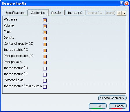


    By default, the Inertia matrix / O, Inertia matrix / P, Moment / axis and Inertia / Inertia matrix / axis system check boxes are not selected and so the corresponding tabs i.e. Inertia / O, Inertia / P, the Inertia / Axis and Inertia / Axis System are grayed out.

  5. Click the Results tab.

    This lets you see the results of the operation: the area, the volume, the mass and the coordinates of the center of gravity.

  6. Click Export tab.

    The options in this tab lets you to specify the geometry to be created and the associativity required or not.

    Note: In VPM Digital Review product, Export tab is not available.

  7. The next step depends on the product you are using. If you are in:

    • VPM Digital Review: Click Create Geometry in the bottom right-hand corner of the Measure Inertia dialog box.
    • Part Design or Generative Shape Design: Click Create Geometry available in the Export tab.

    This creates, from the inertia results, the center of gravity for the principal axes in the geometry of the representation.
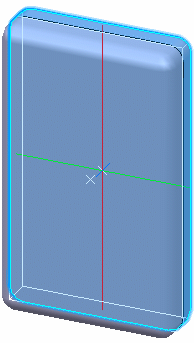


    This also creates center of gravity called Point.x in the specification tree:

    Note:

    • With Associativity option selected: When you create a point, three formulae are created. These three formulae will be displayed in the specification tree inside the relations set . These thee formulae will link the measure knowledge parameters and the parameters of the created points.
    • With Associativity option cleared: No associativity will be there between the created point and the inertia measure. The point cannot be updated to reflect a change in the inertia computation result. If, for example, you move the reference, the point will not be updated.

  8. Click Measure.

    The Measure Inertia dialog box closes.

    Important:
    • Only core material is supported. Covering material is not supported. For information on applying material, refer to the Material Definition User's Guide.
    • 2D inertia is not supported.
    • The inertia computation takes into account all bodies of 3D shape representations.
    • Volumes and surfaces with thickness can be selected.
    • In the Part Design workbench, you can select isolated components of the active 3D shape representation.
    • The default units of measure used are kilos and meters. However, you can change this. For more information, see "Units" in the "Customizing Settings>General>Parameters and Measure" section of the Infrastructure User Guide.
    • If inertia measurement fails, an error message appears. A model cannot be selected for measure inertia calculation. You can however select its parent.
    • Only the actual density of the material is used for inertia measurement purposes. Densities used in specific areas such as simulation cannot be applied.

Use the Different Tabs in the Measure Inertia Dialog Box

You can learn how to use the different tabs in the Measure Inertia dialog box.

For help reading the information provided in the Measure Inertia dialog box, see About Notations Used for Inertia Matrices.

Measure the Principal Axes A About Which Inertia is Calculated

You can measure the principal axes A about which inertia is calculated.

  1. Make sure the Principal axis check box is selected.

  2. Click the Inertia / G tab. This displays the principal axes about which inertia is calculated:


Measure the Inertia Matrix Relative to the Origin O of the Document

You can measure the inertia matrix relative to the origin O of the document.

  1. Make sure the Inertia matrix / O check box is selected.

  2. Click the Inertia / O tab. This displays the inertia matrix of selected items with respect to the origin O:


Measure the Inertia Matrix Relative to a Point P

You can measure the inertia matrix relative to a point P.

  1. Make sure the Inertia matrix / P check box is selected.

  2. Click the Inertia / P tab:


  3. Select the Select Point check box.

  4. Select a point in the geometry area. The coordinates of the point and the inertia matrix are provided in the dialog box.

Important:
  • Once you select a point in the geometry area, the Select Point check box is cleared.
  • Only points created in the Part Design workbench are valid.
  • Selecting another item calculates the inertia matrix of the selected item with respect to the same point. To change the point, reselect the Select Point check box then select another point.

Measure the Moment of Inertia about an Axis

You can measure the moment of inertia about an axis.

  1. Make sure the Moment / axis check box is selected.

  2. Click the Inertia / Axis tab.

  3. Select the Select Axis check box.

  4. Select an axis in the geometry area. The equation and direction vector of the axis as well as the moment of inertia Ma about the axis and the radius of gyration are provided in the dialog box:


Important:
  • Once you select an axis in the geometry area, the Select Axis check box is cleared.
  • Only axes created in the Part Design workbench are valid.
  • Selecting another item measures the inertia of the selected item about the same axis. To change the axis, reselect the Select Axis check box then select another axis.

Measure the Matrix of Inertia Relative to an Axis System

You can measure the matrix of inertia relative to an axis system.

  1. Make sure the Inertia matrix/ axis system check box is selected.

  2. Click the Inertia / Axis System tab.

  3. Select the Select Axis System check box.

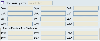
  4. Select an axis system in the specification tree. The name of the axis system as well as the origin O, (U, V, W) -vectors and the inertia matrix with respect to the axis system are provided in the dialog box. Entries for the inertia matrix appear in the specification tree.


Important:
  • Once you select an axis in the geometry area, the Select Axis System check box is cleared.
  • Only axis systems created in the Part Design workbench (using Axis System in the Tools toolbar) are valid.
  • Selecting another item measures the inertia properties of the selected item with respect to the same axis system. To change the axis system, reselect the Select Axis System check box then select another axis system.

Export the Results

You can create a center of gravity geometry and the axis system using Measure Inertia results. Also you can keep the associativity between geometry and the results.

  1. Select the Export tab.

  2. Select the Center of gravity and Axis options to create the respective geometry.

  3. Select Associative to keep the result geometry associative with the primary geometry.

  4. Click Create geometry to create the geometry from Measure Inertia results.