Creating a Breakout View

You can create a breakout view.


Before you begin: Open a drawing representation containing a view from which you want to remove material. Double-click this view to activate it, and make sure it is up-to-date.
Related Topics
More About Breakout Views
Modifying a Breakout View
  1. In the drawing window, click Breakout View in the Views toolbar (Break View sub-toolbar).

  2. Click the first point of the breakout profile.

  3. Click as many points as desired for creating the profile.

  4. Perform either of the following operations:

    • Double-click to end the profile creation and close this profile automatically.
    • Click the profile first point to close and end the profile creation.


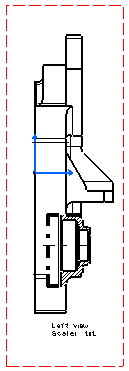
    The 3D Viewer appears, displaying the 3D part corresponding to the generated view. A green arrow indicates in which direction the breakout will be created.

    Important: The 3D Viewer lets you position the 3D part according to a view you go over (on the drawing), provided the Animate option is selected. The 3D Viewer also lets you visualize a view plane and use it to define the depth of the breakout.

  5. Select the Animate option to visualize the 3D part in accordance with the position of the cursor on the generated view.

  6. In the drawing, place the cursor over the front view (which is perpendicular to the left view).

  7. Perform either of the following operations:

    • Directly in the 3D Viewer, drag the plane to the desired location. This method does not let you define the depth of the breakout precisely. The breakout will not be associative with any element.
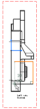
    • In the drawing, place the cursor over an axis, a center line or an edge (circular or linear) of a perpendicular view. The 3D plane will be moved accordingly. This method lets you break the view through a hole or a face, for example. The breakout will be associative with the selected element. For example, place the cursor over the center line that will be used as an extremity plane, as shown below.

      The plane is moved accordingly in the 3D Viewer.

    • In the 3D Viewer, click the Reference element field to select it. Then, in the drawing, select the edge which corresponds to the face that will be used as a reference element to define the depth of the breakout, and enter the depth in the Depth (in mm) field (you can also define the depth by moving the red plane with the mouse). This method lets you define the depth of the breakout precisely. The breakout will be associative with the selected reference element and with the depth value.


  8. Click OK in the 3D Viewer.

    The breakout view is created.