About View Creation | |||||||
|
| ||||||
Behavior of Graphic Properties at View Creation
This sub-topic explains the behavior of graphic properties that govern the creation of generative views.
First of all, you need to understand that several elements are taken into account to define the graphical properties of generative views, according to a precise priority order. Some apply at view creation, some apply once a view has been created. This enables you to comply with the chosen standard, while answering your corporate or individual customization needs.
The following elements are taken into account to define the graphical properties of generative views at the time of their creation:
Once a view has been created, you can customize its graphic properties in several ways: by editing its generation properties, by overloading its properties and by modifying the graphical properties of generated geometry and dress-up. For more information, refer to About View Content Customization and About the Graphical Properties of Generated Geometry.
![]()
Settings Defined in Tools > Options
The settings defined in Tools > Options > Mechanical > Drafting > View tab let you customize the default values used when creating views in Generative Drafting.
![]()
Generative View Styles (GVS)
Generative view styles (GVS) are defined by an administrator and specify the styles of a generative view, that is to say its appearance and behavior. GVS are applied on a view per view basis, at the time of view creation. Using GVS is optional.
Views are linked to the GVS they were created with. Therefore, if you overload the properties (see below) of a view created using GVS, you can reset the GVS, which cancels the overload.
For more information on using GVS, refer to Working with Generative View Style.
![]()
The Active View
This sub-topic explains what the active view is.
The active view is the view from which other views will be generated. It could be viewed as the "parent" view. It is also the view in which all modifications (such as adding 2D geometry and dress-up elements) will be performed.
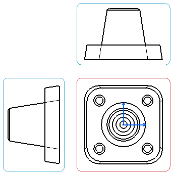
In a drawing representation, the active view is represented using a red frame and it is underlined in the Drafting specification tree.
Note: Inactive views are represented with blue frames. During view creation, the view to be created has a green frame until you click at the desired view location to validate the creation.
To activate an existing view, you can either double-click the view frame or right-click the view and select Activate View.
Axes are taken into account on the active view only. As a result, the active view frame will adapt to the elements included in this view.
![]()
View Frame
For views located in design sheets, the view frame has rounded corners and it is displayed using a solid linetype.
The following table depicts the type of view frame color each view has:
| View | View frame color |
|---|---|
| Active | Red |
| Projection | Blue |
| Section | Green |
| Section cut | Yellow |

![]()
View Text
The view name and the view scale are displayed in the view as per the settings done by the administrator. For more information, refer to Managing View Texts.
As there is no link between settings and views, modifying these settings does not modify the properties of existing views. However, views that are created afterwards will be impacted by the modification of settings.
For more information on view settings customization , refer to View.
![]()
Generative View Positioning Mode
This sub-topic explains how generative views are positioned.
Generative views are positioned according to the center of gravity of the 3D part. If you modify a 3D part in such a way that the center of gravity of the part changes, then, when updating the view, the position of the view will be re-computed according to the new center of gravity of the part and will be modified accordingly.
![]()
Part and Product Attributes and Options Impacting View Creation
This sub-topic provides information on how some attributes and options defined for parts and products have an impact on view creation.
The following are discussed:
![]()
Operations Performed on Parts
Operations performed on parts, and that can be propagated with the part itself (such as Show/No Show, Delete, Deactivate, Visualization Filters, etc.), are taken into account when generating the view. For example, if you swap a part body to invisible space (No Show), this body will not be represented on the generated view. If you then swap this part body to visible space (Show), you can update the corresponding views; this time, the body will be represented on the generated view.
Important:
When the No Show property is applied to:
|
There is an exception to this rule: when generating views in exact mode, Define in Work Object is not taken into account. However, since this command is taken into account when generating views in CGR, Approximate and Raster modes, it is it is recommended to be wary of using Define in Work Object for such view types.
![]()
3D Shape Infrastructure Settings
Settings used for a given part, and that only have an impact on the current session but cannot be propagated with the part itself (such as the Display in Geometry Area category of settings available via ), have no impact on how or whether the part will be represented on the generated view.