More about Grills | ||||
|
| |||
About Profiles
To create a grill, you need a profile that defines the boundary of the grill and optional profiles for interior geometric components called ribs, spikes and island.
The grill feature can be placed onto shape features (except protected features) and functional features (except the protected volumes of protected pocket and protected pull).
If you are not satisfied with the profile you selected, note that you can:
- Click the Profile/Surface box again and select another sketch.
- Use any of these creation contextual commands available from the
Profile/Surface box:
- Go to profile definition. For more information, see Part Design User's Guide: Sketch-Based Features: Pads: Using the Sub-Elements of a Sketch
- Create Sketch: For more information, see Sketcher User's Guide: Creating a Positioned Sketch
- Create Join: Joins surfaces or curves. For more information, see Generative Shape Design User's Guide: Performing Operations on Shape Geometry: Joining Surfaces or Curves
- Create Extract: Generates separate elements from non-connex sub-elements. For more information, see Generative Shape Design User's Guide: Performing Operations on Shape Geometry: Extracting Geometry: Extracting Elements
![]()
Tab Options
The following tabs let you define the grill that fits your needs.
Boundary:
The Outer Height box allows you to define the height of the grill outside the shellable feature. It also allows the grill geometry to protrude outside of the volume. In the final feature (not the quick preview), this is measured from the outside face of the shell body.
The Inner Height box allows you to define the height
of the grill inside of the shellable feature. In the final feature
(not the quick preview) this is measured from the outside face of
the shell body.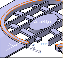
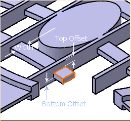
Ribs:
Rib geometry is optional.
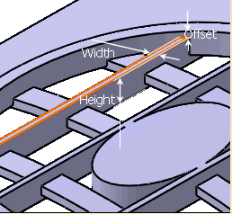
Spike:
Spike geometry is optional and is typically similar to rib
geometry. The top and bottom surfaces of the spikes are defined
through offsets from the top and bottoms surfaces of the ribs.
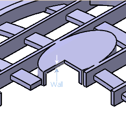
Island:
To define the island wall thickness, you can set one of the two options available from the Type drop down list:
- Use body thickness: The island wall thickness is taken from the bodies shell properties feature.
- Enter thickness: Simply enter the value you want. When this option is selected, the value box becomes available. A value of zero will be interpreted as "no walls", i.e. solid geometry will be produced.
Draft:
If you want to define a draft angle, just click the Draft tab.
The Draft behavior list provides following options:
- None: There is no draft.
- Intrinsic to feature: You can perform a draft operation by defining the following parameters:
- an Angle value. You can enter the angle value you want.
- a Neutral element (defines a neutral curve on which the drafted
face will lie) that can be:
- Profile plane
- Ceiling
- Opening
- Plane/Surface
- Draft Properties: You can access draft properties defined in the solid functional
set.
At the selection of draft properties in the dialog box, all the
draft properties located in the document are displayed in the
Draft behavior box. You can select any of them (Draft Properties.x) for creating a grill. In this case, a new Use parting element option is added in the Neutral element box.
Note: You need to define draft properties prior to the creation of the grill to choose Draft Properties in the Draft behavior list.
Fillet:
Select the Lateral radius check box to fillet lateral edges. Then, you merely need to set the radius value of your choice.
By using Lateral radius and Fillet profile ends, you can apply fillets at the intersection or at the ends of the open profile of the reinforcement. See Creating a Prism for some examples.
If you want to add an intersection fillet, select Intersection with Cavity in the Intersection Fillet box.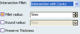
If you want to add material to the feature, select the Fillet radius checkbox. If you want to remove material from the feature, select the Round radius checkbox.
Select the Preserve Thickness checkbox if you want to keep the thickness applied on the feature.