Creating Sweep 3D Meshes

You can mesh a solid part by generating hexahedron elements (HE8 and HE20) and wedge elements (WE6 and WE15) from surface meshes.

The sweep 3D provides volume mesh (Linear Hexahedron, Parabolic Hexahedron, Linear Pentahedron or Parabolic Pentahedron) from a surface mesh. When possible, neighboring lateral and top meshes are captured to provide a solid mesh without interference. To generate a sweep mesh, the volume must be assimilated to a prism with a top and a bottom.


Before you begin: A finite element model representation that contains 2D meshes must exist.
Related Topics
Finite Element Model Representations
Meshing 2D Geometries
Updating Meshes
Creating 3D Properties
Elements
  1. In the Meshes toolbar, click Sweep 3D Mesh .

    The Sweep 3D Mesh dialog box appears.

  2. Select the geometric support.

  3. Select the element type (Linear or Parabolic).

  4. Select the sweep limits.

    1. Select the surface mesh that is the source (bottom) of the sweep mesh (Sources).
    2. Click the Targets box to activate it, and select the target (top) domain (Targets).

  5. Optional: In the Angle box, enter a value to specify the tolerance angle between two curves to compute the guides.

    Guides are limits that constrain the solid mesh between the source and the target faces.

  6. Optional: Click Compute Guides to find automatically guides.

    The guides are computed and are highlighted in yellow.

    In the following example, all the existing meshes are hidden, the face highlighted in blue is the source, the face highlighted in red is the target, and four guides have been computed:
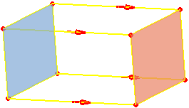


  7. Optional: To remove the results of the guide computation, click Remove Guides.

  8. Optional: To include edges in the guide computation, click .

  9. Optional: To exclude edges from the guide computation, click .

  10. Optional: In the Mesh tab, modify the distribution.

  11. Optional: In the Mesh tab, modify the target smoothing.

  12. Optional: In the Mesh tab, capture updated meshes.

  13. Click one of the following:

    • Cancel to cancel the modifications and close the dialog box.
    • Apply to save the parameters you defined and to create, update, and generate the mesh.

      The PLM Update progress bar appears. You can interrupt the update. See Updating Meshes.

      The Sweep 3D Mesh dialog box remains open to continue modifying parameters if necessary.

    • OK to save the parameters you defined, to create the mesh, and to close the dialog box. To generate and visualize the mesh, you have to update it. See Updating Meshes.

    If you click Apply or OK, the 3D mesh is created and appears in the specification tree.