Editing the Topology | |||||||
|
| ||||||
In the Mesh Edition toolbar, click Edit Topology
 .
.
You enter the topology edition mode and you access several tools to modify the topology.
By default, the edition mode lets you add or remove edge constraints. Each time you select a new option using the contextual menus, and depending on the type of geometry you select, the selected mode becomes the current edition mode.
Important: The topology edition tools vary depending on whether you selected the Geometry Simplification check box in the global parameters of the surface mesh and if you launch the simplification or the mesh execution. To constrain an edge, right-click a non-constrained edge (colored in blue), and select Add/Remove Edge Constraints.
If the edge constraint is the current edition mode, you can pass your cursor over a non-constrained edge, and select it when the following symbol appears:
The edge is constrained and is colored in yellow:

To remove an edge constraint, right-click a constrained edge (colored in yellow), and select Add/Remove Edge Constraints.
If the edge constraint is the current edition mode, you can pass your cursor over a constrained edge, and select it when the following symbol appears.
The edge constraint is removed and the edge is colored in blue:
To constrain a hole, right-click a non-constrained hole (colored in blue), and select Add/Remove Hole Constraints.
If the hole constraint is the current edition mode, you can pass your cursor over a non-constrained hole, and select it when the following symbol appears:

The hole is constrained and is colored in green:

To remove hole constraints, right-click a constrained hole (colored in green), and select Add/Remove Hole Constraints.
If the hole constraint is the current edition mode, you can pass your cursor over a constrained hole, and select it when the following symbol appears:

The hole constraint is removed and the hole is colored in blue:

To remove vertex constraints, right-click a vertex, select Add/Remove Vertex Constraints, and select constrained vertices (colored in yellow) in sequence.
You can also pass your cursor over a constrained vertex, and select it when the eraser symbol appears.

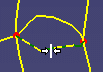
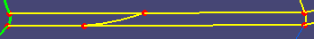
Important: You cannot remove vertex constraints for vertices that connect more than two edges (vertices that are colored in red). Consider the following example:

The result is:
To collapse edges, right-click the edge, and select Collapse Edge.
The following symbol appears:

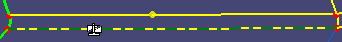
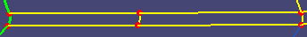
Collapsing an edge allows you to transform an edge with two vertices into a single vertex. Consider the following example:

The result is:
To cut edges, right-click an edge, and select Cut Edge.
You can select other edges in sequence to cut them. A scissors symbol is displayed when you move your cursor over a constrained edge:
The edge is cut and a vertex is created at the cursor position:
To merge edges, right-click the first edge, select Merge Edges, and select the second edge.
The two edges are merged: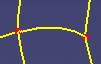
To split a domain by creating two vertices:
- Click the other edge where you want to add the second vertex.
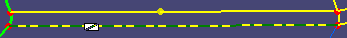
Tip: Use the Ctrl key to split domains in sequence. A second vertex is created at the cursor position and the domain is split:
- Click the other edge where you want to add the second vertex.
To split a domain orthogonally:
- Click the other edge.
Tip: Use the Ctrl key to split domains in sequence. A second vertex is automatically created on the second edge and the domain is split:
- Click the other edge.
To exit the topology edition, click Edit Topology
again.