Setting the Global Parameters of a Surface Mesh | ||||||
|
| |||||
If you are already in the surface mesher workshop, click Global Parameters
 in the Global Specification toolbar.
The Surface Mesh dialog box appears. The Mesh tab allows you to set the global mesh parameters (for example: mesh size, element shape, sag...) and the Geometry tab allows you to set the global topologic parameters (for example: offset, ignore internal cracks...).
Select the 2D geometry you want to mesh.
Select the Mesh tab to define the mesh parameters.
Select the element shape.
- To mesh the surface with only triangle elements, click
Trias Only
 .
. - To mesh the surface with quadrangle elements when it is
possible, click Quads Dominant
 .
. - To mesh the surface with only quadrangle elements, click
Quads Only
 .
.
- To mesh the surface with only triangle elements, click
Trias Only
Select the element type: Linear or Parabolic.
In the Mesh size box, enter the value for the global size assigned to the mesh.
Optional: If you selected Quads Only, you can choose a default mesh method by selecting the Default method check box.
Optional: If you selected Trias Only, you can specify sag specifications.
The absolute sag is the is the maximum gap between the mesh and the geometry. The proportional sag is the ratio between the local absolute sag and the length of the local mesh edge.

Important: Proportional sag value= (local Absolute sag value) / (local mesh edge length value). You can use both absolute sag and proportional sag; the more constraining of the two values is used.
Optional: To capture nodes and edges of elements from the neighbor meshes in order to obtain a compatible mesh:
- Select the Automatic mesh capture check box.
- In the Tolerance box, enter a maximum distance to capture nodes and edges of elements of the selected meshes.
- By default, all the meshes of the finite element model representation are selected (All in the Apply on box). To modify the list of meshes to be captured, activate the Apply on box and select the desired meshes.
Once you select a mesh, the Edit Selection
 button becomes available. This button lets you visualize or modify the meshes to be captured. You can select other meshes, remove all the meshes from the selection, remove a particular mesh, reframe the 3D view on a particular mesh, and center the specification tree on a particular mesh.
The mesh capture is performed using the condensation mode; that is to say that the nodes of the captured mesh and the surface mesh are shared, they are not duplicated. The mesh capture is performed dynamically on all constraints (free edges, internal edges...) and after all constraints modifications.
Select the Geometry tab to define the geometric parameters.
Optional: By default, the global geometry size is equal to the global mesh size and is fixed using a knowledge formula. So if you change the value in the Mesh size box of the Mesh tab, the value of the Geometry size box is modified accordingly. You can remove the formula, edit it...
Optional: In the Angle between faces box, enter a value that specifies the minimum angle between faces to constrain the common edge.
Optional: In the Angle between curves box, enter a value that specifies the minimum angle between curves to constrain the common vertex.
Optional: In the Curvature angle box, enter a value that specifies the minimum angle to take into account the curved surfaces.
Optional: In the Offset box, enter a value to define an offset.
Optional: To ignore holes, select the Ignore holes smaller than check box, and enter a value under which you want to ignore holes.
Optional: To ignore internal cracks, select the Ignore internal cracks check box.
Optional: To merge edges during the topology simplification, select the Geometry simplification check box, and enter a value in the Minimum size box to specify the minimum size of topological edges.
Whenever possible, edges are merged if they are smaller than the specified value or if the distance between two edges is less than the specified value.
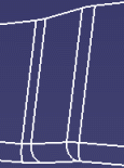
Important: If you clear this check box, the topology simplification tools will not be available. Consider the following geometry:

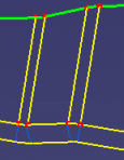
Result of the topology simplification when the Geometry simplification check box is cleared:
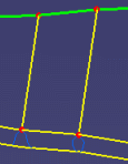
Result of the topology simplification when the Geometry simplification check box is selected:

Optional: To find out all external curves located near the geometric support of the surface mesh under a given tolerance and to project them automatically to create external constraints, select the Automatic curve capture check box.
Click OK.