More About Image Edition | ||||||
|
| |||||
Data Parameters
You can modify the data parameters of an image.
| Important: The Data tab is not available for deformed mesh images. |
The data parameters are:
Criterion
Provides a list of visualization criteria. The content of the list
depends on the edited image.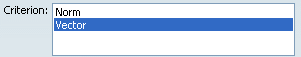
Values
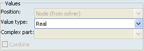
- Position
- The position depends on the selected Type and
Criteria options. See Structural Analysis User's
Guide: Reference Information: Post-Processing and
Visualization.
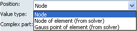
Node Linked to the mesh nodes. For each node, there is only one value. It is possible to have more than one value in case of tensor images. If a node is shared by two elements with different dimensions (for example, 1D-dimensional and 3D-dimensional elements), you will get two values since the tensor is different between the two elements. Node of element For each node, there is as many values as elements linked to this node. Center of element For each element center, there is only one value. Edge of element For each edge element, there is only one value. Face of element For each face element, there is only one value. Element For each element, there is only one value. Gauss point of element The position of the Gauss points depend on the type of element. For more details, see Finite Element Modeling User's Guide: Reference: Elements. (from solver) Indicates that the position is provided by the solver. - Value type
- Corresponds to the type of the value (integer, real, double precision, complex, complex with double precision).
- Complex part
- The complex part is available when the selected Value Type is complex and complex with double precision.
- Combine
- If this option is activated, combined values will be displayed whenever available. The desired resulting force will be displayed.
- If this option is not activated, each specification (force, restraints and so forth) can be displayed separately. You will use the Value set list box to choose the desired value set.
For example, if three forces were applied on a single surface, three values will be available in the Value set list box. You can then select the desired Value set.
Filters
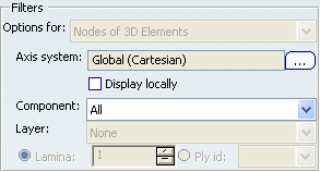
- Options for
- Lets you select the entity type on which you will change the Axis system, Component, Layer,
Lamina and Ply id
options. This option does not modify the feature you are editing.
The following options are available:
- Nodes of 1D elements, Nodes of 2D elements, or Nodes of 3D elements for a Node position type.
- 1D elements, 2D elements, or 3D elements for an Element position type.
- Axis system
- Lets you select the current axis system to be used. The
 button is available only if the selected criterion is
Vector, Tensor, Vector component
or Tensor component.
button is available only if the selected criterion is
Vector, Tensor, Vector component
or Tensor component. Important: The availability of this option depends on your available licenses. See Licensing. To modify the axis system, see Modifying the Axis System and Coordinate System.
Important: For nodal coordinate image: - The tangential component (y) is equal to zero in cylindrical coordinate systems.
- The circumferential and meridional components (y and z) are equal to zero in spherical coordinate systems.
- Display locally
- Lets you visualize locally the axis on each entity.
Important: The availability of this option depends on your available licenses. See Licensing. - Component
- Lets you select the components you want to visualize.
For example, if you selected a translational displacement image, you get the following component options:
- All: all the components.
- C1: components according to x in the current axis system.
- C2: components according to y in the current axis system.
- C3: components according to z in the current axis system.
- You can also have a combination of these components (for example C1&C2).
For a stress principal tensor image:
- In case of 3D elements, the possible component options are C11 (maximum principal stress), C22 (middle principal stress), and C33 (minimum principal stress). You can also have a combination of these component.
- In case of 2D elements, the possible component options are C11 (maximum principal stress) and C22 (minimum principal stress).
Important: If the components selected for 1D, 2D, and 3D elements are different, the All option will be empty to show you that the selected components are not equal. - Layer
- This option is available only for 2D elements.
You can select the Upper, Middle, Lower, or Upper and lower layer from which the results will be computed.
For 2D composite properties, the Layer option is available only if the composite property is defined with the zone approach (see Finite Element Modeling User's Guide: Creating Structural Properties: Importing Composite Properties). In this case, the Upper, Middle and Lower options correspond respectively to the top, the middle and the bottom of the stacking.
Important: If the layers selected for 1D, 2D, and 3D elements are different, the Layer box is empty to show you that the selected layers are not equal. - Lamina
- This option is available only for 2D elements with composite property.
You can select the lamina from which the results will be visualized.
- Ply id
- This option is available only for 2D elements with composite property.
You can select the ply from which the results will be visualized.
Important: If the 2D element has an - imported composite property defined by ply, the Ply id list displays the name of the plies defined in the Composite Design Workbench and appearing in the specification tree.
- inhomogeneous composite property defined in an XML mapping property, the Ply id list displays the ply identifiers.
Warning: The computation is based on the order given by the Lamina option and not on the order given by the Ply id option. The Ply id option is not aimed to visualize the exact way the stacking has been defined. To visualize what happens physically when you perform a core sampling, use the Lamina option.
Limits
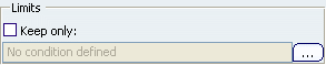
The Keep only option lets you ignore or not values in the image. If you select this check box, you have to specify a condition
according to which the values shown in the image should be
filtered. If you do not select this check box, all the values of
the image are kept.
This option is available only for scalar and vector mathematical values and only in the image edition context.
Click to define the condition. The
Interval dialog box appears.
The condition is defined by:
- Values or Absolute values
- An operator: greater than, less than, greater than or equal to, less than or equal to, between, not between, equal to, not equal to.
- A threshold value or an interval.
![]()
Display Parameters
You can modify the display parameters of an image.
Visualization
Gives you the choice between different visualization types.
Deformed mesh images have no visualization type. The list of
visualization types depends on the selected image and the position selected in the Data
tab:
- Average iso: lets you visualize isoclines at nodes. This visualization type uses the Material Rendering capabilities.
- Discontinuous iso: lets you visualize isoclines at nodes of element. Visualizing isoclines at nodes of elements may induce a color discontinuity from an element to an other. This visualization type uses the Material Rendering capabilities.
- Fringe: lets you color an element, a face of element or an edge of element according to the scalar value defined for this entity.
- Text: lets you visualize results using text.
- Symbol: lets you visualize results using symbol. The available symbols depend on the values to be displayed.
| Visualization types | Node position | Element position |
|---|---|---|
| Average iso | Node | |
| Discontinuous iso | Node of element | |
| Fringe | Edge of element Face of element Element Center of element |
|
| Symbol | Node | Face of element Element Gauss point of element Center of element Node of element |
| Text | Node | Face of element Element Gauss point of element Center of element Node of element |
The solver process gives results only for certain positions that are not always authorized or really useful. Results need to be post-treated. The post-treatment can be either a smoothing (element to node) or an extrapolation (node to element).
For a smoothing post-treatment, average values are computing as follow: the solver process takes into account all the elements linked to a node, but a weighting is done according to the distance between this node and the center of gravity of the elements.
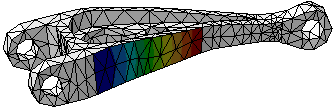
The following image shows an example of a visualization
list: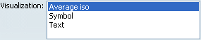
Options
The display options vary depending on the visualization type you selected.
- Display free nodes: lets you display free nodes (nodes that are not referenced by any element).
- Display nodes of elements: lets you visualize nodes of elements.
- Display small elements: lets you choose to display or not the very small elements.
- Shrink Coefficient: lets you shrink the element visualization.
- Display elements without value: lets you display elements with or without value.
- Display elements outside selection: lets you display
the elements which are not in the current selection (Activated
Groups in the Selections tab) with a white color.
The following image shows you an example:
- Type:
- Representation: lets you choose between the symbol representation types. The number of the available representations depends on the selected criterion and the selected visualization.
- With text: lets you display the values corresponding to each displayed symbol. You can change the text properties settings using the menu. See Images.
- Color:
- Imposed: enables the color to be fixed. If this option is selected, you can use the color chooser.
- Size:
- Minimum length: lets you define the minimum symbol length.
- Maximum length: lets you define the maximum symbol length.
- Variable: enables the variability of the symbols in function of the value.
- Zoom sensitive: enables the length of the symbols to be zoom sensitive.
The following image shows an example of the display options for a symbol visualization: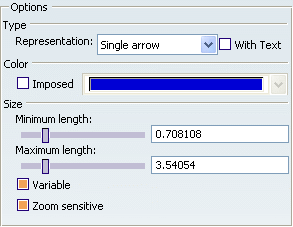
![]()
Selection Parameters
You can modify the selection parameters of an image.
By default all the model is
visualized. The Selections tab lets you limit the image
visualization to a list of entities, where entities can be:
- Meshes (under the Nodes & Elements set in the specification tree).
- Excitations (under the Restraints, Loads and Masses sets in the specification tree).
- User groups of elements, element edges, and element faces (under the Groups set in the specification tree).
- Available Groups
- Lists all the available entities.
- Activated Groups
- Shows you the list of the entities you have activated the visualization. By default all the model is visualized.
The Available Groups list gives you the list of the available entities. You can select entities that are not displayed in the Available Groups list directly in the specifiction tree or in the 3D view. You can also use the power input or the find capability.
Activated Groups shows you the list of the entities you have activated the visualization.
![]()
Occurrence Parameters
You can modify the occurence parameters of an image.
| Important: The Occurrence tab is available only for images generated under a multi-occurrence solution. |
The Occurrence tab lists the modes with the associated frequencies (for a frequency solution or a harmonic dynamic solution), buckling factors (for a buckling solution), time (for a transient dynamic solution).
You can change the displayed occurrence by selecting a line in the list and activate separately each mode of a multi-occurrence solution. By default, the first occurrence is displayed. The selected occurrence and its associated value are displayed in the color map.