Creating a Cutout | |||||
|
| ||||
Create a Cutout Using a Sketch or a Wireframe
You can create a cutout using a sketch or a wireframe.
Click Cut Out
 in the
Cutting/Stamping toolbar.
in the
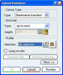
Cutting/Stamping toolbar. The Cutout Definition dialog box is displayed and the skin to be impacted by the cutout is displayed in a different color.
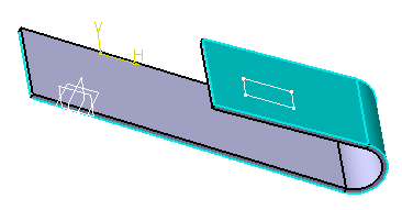
Select a profile (Sketch.xxx).
Warning: - The sketch you select can be either a sketch containing one or more shapes, a wire, or a part.
- You are strongly advised to use a
closed profile to create a cutout. In case you create a cutout from a profile
containing more than one open contour, you are warned that the cutout may fail.
In this case:
- Click Yes in the error message to select the profile anyway
- Click OK to create the cutout.
- If the
cutout fails, modify the profile in the Sketcher workbench or click
No.
The profile is not selected.
- Once the sketch is selected, you
can modify it by clicking
 .
.
Important: - The Reverse Side option lets you choose between removing the material defined within the profile, which is the application default behavior, or the material surrounding the profile.
- The Reverse Direction option allows you to invert the direction of the extrusion pointed by the arrow.
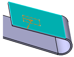
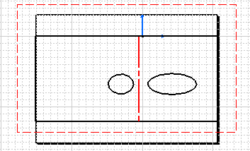
A preview of the projected cutout is displayed. The vectors show the side and the direction of the cutout.
Click OK in the Cutout Definition dialog box.
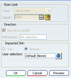
Important: Several End Limit types are available: - Dimension
- Up to next
- Up to last
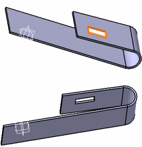
The cutout is created.
Click More>> to display the maximum information.
The Direction is already selected (Sketch.xxx), that is perpendicular to the base feature.
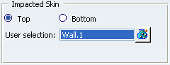
Note: Here the cutout impacted skin is set to Default, that is, the surface on which lies Sketch.xxx.
Click
 and select a
new support for the cutout.
and select a
new support for the cutout. Tip: You can choose a web, a flange or the planar part of the surfacic flange as support. Important: Specifying the support for the cutout avoid confusions in case of overlaps. The Support selection dialog box is displayed.
Select the opposite wall as your new support for the cutout.
Tip: Should you want to perform a cutout on the opening line (unfold reference) of a rolled wall or a hopper, you must select the rolled wall or the hopper feature as the support for the cutout. Click OK in the Cutout Definition dialog box.
The cutout is created on the opposite wall.
Important: - When Lying on
skin check box is selected:
- The End Limit and Start Limit types are automatically set to Dimension and are not available
- The Depth is set to 0mm and is not available
- The skin to be impacted is displayed on the part. The cutout is not projected anymore on the skin. It is based on a sketch that inevitably lies on a surface. This option is available only when creating a standard cutout.
- In case the profile edges and the impacted skin to extrude are tangent, the sketch becomes non-valid and the cutout cannot be created. To avoid this, select Lying on skin check box or select a base feature as support to be able to create your cutout.
- When Lying on
skin check box is selected:
![]()
Create a Cutout Using a Support Different from a Sketch or a Wireframe
You can create a cutout usinga support different from a sketch or a wireframe.
Click
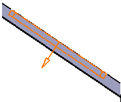
. The Cutout Definition dialog box is displayed and the skin to be impacted by the cutout is displayed in a different color.
Right-click the Selection field from the Profile frame to select the profile you want.
Tip: You can also select a profile directly in the geometry or click  .
.The End Limit options are not available.
Note: Click More>> to display the maximum information. You can see that the Start Limit and Direction fields are not available either.
![]()
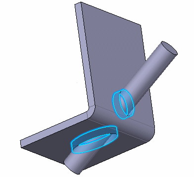
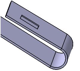
Create a Cutout to Let a Cylinder Get through a Sheetmetal Part
If you want to have a cylinder get through a sheetmetal part, you can create only one cutout that cuts the bottom skin and the top skin at the same time.
Click
. The Cutout Definition dialog box is displayed.
![]()
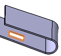
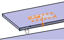
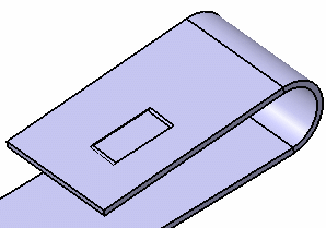
Create a Pocket Cutout
You can create a pocket cutout.
Click
. The Cutout Definition dialog box is displayed.
Select Sketch.xxx as profile.
A preview of the cutout is displayed. In our example, the cutout will impact only half the base feature.
Click OK in the Cutout Definition dialog box.
The cutout is created.
Select a line to perform a cutout normal to the line direction.
Tip: Right-click the Reference field and select the to create a line. Click OK to create a cutout normal to the line direction.
Warning: - If you want to create a cutout on an overlapping element or a bend with radius=0, either choose the top skin of the element (as shown in the picture above), or unfold the part to create the cutout.
- You cannot create a pocket cutout on a stamp or a surfacic flange.
- You cannot create:
- a standard cutout on a pocket cutout
- a standard cutout on a feature impacting a pocket cutout.
- Once the Reference Direction and the Objects Support fields are filled in, the selection can be modified but cannot be cleared.
Important: - Cutouts can be created directly on the of the part.
- Refer to Component Catalog Editor documentation to have further information on how to use catalogs.
- Refer to Creating a Pocket task in the Part Design User's Guide for further details on how to create cutouts.