Creating a Hole | |||||
|
| ||||
Create a Hole
You can create a hole.
Click Hole
 in the Cutting/Stamping toolbar (Holes sub-toolbar)
and click the surface where you want to place the hole.
in the Cutting/Stamping toolbar (Holes sub-toolbar)
and click the surface where you want to place the hole.A grid is displayed to help you position the hole.
The Hole Definition dialog box is displayed, providing default values.
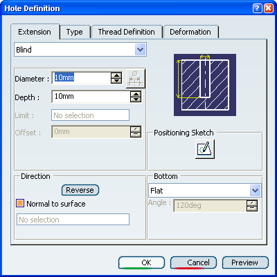
In the Extension tab, choose a bottom limit for the hole.
Blind Up to Next
 Up to Last
 Up to Plane
 Up to Surface
Choose a bottom type for the hole.
-
Flat;
-
V-Bottom;
-
Trimmed (available when selecting Up to Next, Up to Last, Up to Plane or Up to Surface).
In our example, we selected a V-Bottom of 120 degrees.
-
In the Type tab, select the type of hole you wish to create.
Simple Tapered
 Countersunk
 Counterdrilled
 Counterbored
Click OK to create the hole.
Important: - If you want to create a hole on an overlapping element or a bend with radius=0, either choose the top skin of the element, or unfold the shape to create the hole.
- You can create:
- A hole on a hole
- A hole on a half-height hole
- A hole on a pocket
- A hole on a hole
![]()
Create a Hole with No Deformation
You can create a hole with no deformation.
Before you begin: Create a wall or a web with a cylindrical bend or a flange.
Select the Deformation tab in the Hole Definition dialog box.
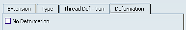
You can choose either or not to select the No Deformation check box:
Deformation
No Deformation
By default, No Deformation option is not selected.
Warning:
When the
No Deformation option is not selected:
|
![]()
Change the Position of a Hole on a Surface
You can change the position of a hole on a surface.
If you need to change the position of the hole on the surface:
Click Positioning Sketch
 .
The Sketcher workbench opens and a point representing the
hole's position is displayed on the surface.
.
The Sketcher workbench opens and a point representing the
hole's position is displayed on the surface.
Move the hole on the surface according to your needs.
Exit the Sketcher workbench. The hole is positioned according to your settings.
![]()
Constrain the Location of a Hole
You can constrain the hole's location when creating it.
Select two edges on the wall and click Hole
.Click the surface where you want to place the hole.
Constraints defining the distances between the hole's center and the edges are displayed.
Click OK to create the Hole.
Refer to Part Design User's Guide : Sketch-Based Features : Holes : Locating Holes for more information.