Accessing the Structural Analysis Workbench | ||||
|
| |||
From the bar, click
 ,
and select Simulation > Generative Analysis > Structural Analysis.
,
and select Simulation > Generative Analysis > Structural Analysis.Each time you enter the Structural Analysis workbench using this icon, a new structural analysis simulation is created. Depending on whether a product is open and displayed or not, the use of the
 icon gives different results:
- If no product is open, the Structural Analysis / Simulation dialog box appears. You can save the simulation in the database, and you have to associate a product with this simulation before defining the structural analysis simulation specifications.
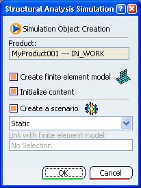
- If a product is open, the Structural Analysis Simulation dialog
box appears.

The options available in the Structural Analysis Simulation dialog box vary depending on whether the product contains several 3D shapes or not.
Optional: If no product is open, modify the name of the simulation in the Name box of the Structural Analysis / Simulation dialog box, and click Finish.
You enter the Structural Analysis workbench, and a structural analysis simulation is created.

Optional: To create a new finite element model representation, select the Create finite element model check box.
To learn more about the creation of finite element model representations, see Accessing the Finite Element Modeling Workbench. To learn more about finite element model representations, see Finite Element Model Representations.
Optional: To use a finite element model representation that is already contained in the product, clear the Create finite element model check box.
- If the product contains only one finite element model representation, this finite element model representation is selected automatically and its name appears in the Link with finite element model box.
- If the product contains several finite element model representations, you have to select in the specification tree the finite element model you want to use.
Optional: To create a scenario, select the Create a scenario check box, and select one of the following:
- Static to create a static scenario.
- Frequency to create a frequency scenario.
Click OK.
The Finite element model / Representation dialog box appears.
Optional: In the Representation Name box, modify the name of the finite element model.
Click Finish.
The Structural Analysis / Simulation dialog box appears.
Optional: In the Name box, modify the name of the structural analysis simulation.
Click Finish.
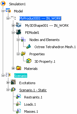
All the needed categories are created. A 3D mesh part and a 3D property have been created.
This is an example of what you obtain if you have selected the three check boxes and Static:

Important: The finite element representation is automatically hidden when you enter the Structural Analysis workbench.