Arranging Segments in Supports | |||||
|
| ||||
Select Tools > Segment Arrangement > Arrange Segments
 .
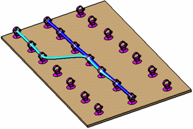
.
You are prompted to select a support.
Note: This command cannot be used for retainers since segments are automatically positioned along these supports and cannot be re-arranged.
Select a support.
The Arrange Segments dialog box appears. Branches passing through the selected support are listed.
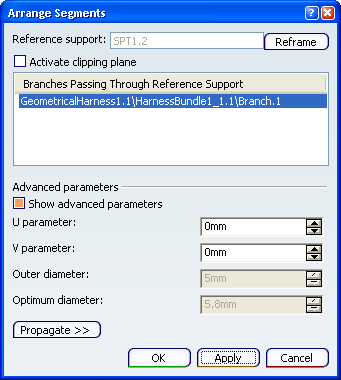
The selected branch is highlighted in the geometry area.
When the Reframe button is clicked, the view point is modified so that you can rearrange the segments more easily by having a face view of the support.
When you select the support and click Arrange Segments, the view point is modified automatically and at the end of the command, the initial view point is retrieved.
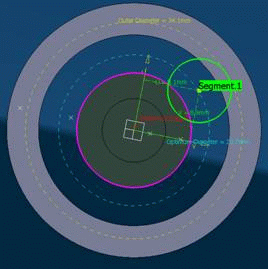
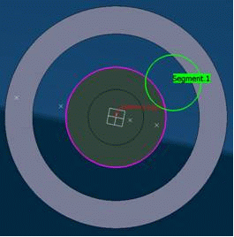
Select the Show advanced parameters check box to display the segment's parameters in the geometry area. This option is selected by default.
When this option is selected:
When this option is cleared:
Click Reframe to center the 3D view on the selected support and set the support parallel to the screen.
Select the Activate clipping plane check box to better visualize the selected support.
U and V axes are displayed in the geometry area. The origin of the 2D U, V axis system is positioned on the center of the support. The Outer and Optimum Diameters are also displayed.
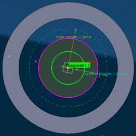
When the clipped view is rotated, you can observe that the center curves of the segments temporarily disappear.
-
A circle is displayed to highlight the cross-sections of each passing segments. These cross-sections will get the color of their irrespective segment.
-
The circles representing each segment sections, will have a diameter equal to the diameter of the larger covering protection at the support location.
-
While (only) the clipping plane is activated, the branch center curves are hidden; they are shown back when the clipping plane is deactivated.
-
The manipulators move freely in all directions, but the U and V parameters value are still displayed in the 3D as well as in the dialog box. The plain cross shapes follow the manipulator, whether the geometry is updated or not. In other words the shapes are not linked to the segments themselves.
-
The segment geometries are updated only after clicking the Apply button. This improves the overall performances.
-
For multi-profile segments, the displayed manipulator will be a circle with diameter equal to the equivalent diameter of the segment.
-
In the geometry area, move the segment to the desired location inside the support.
Use the green tool to assist you move the segment to the desired location along U and V axes. This tool is positioned on the center of the segment. U, V parameters give the distance of the segment from the center of the support.

U, V parameters in the dialog box are updated accordingly.
Note: You can also arrange the segment inside the support by modifying the U, V parameters directly in the dialog box.
Select another branch in the list and adjust to desired location inside the support.
The entire branch is highlighted in the geometry area.
Repeat as necessary to arrange all branches routed through the selected support.
Click Propagate>> to expand the dialog box.
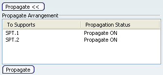
Important: You can propagate the segment arrangement through all the supports listed under the Propagate Arrangement area. Note that all supports through which the selected branch is routed are listed in the dialog box. They are also identified by a Propagate ON label in the geometry area. You can choose to individually propagate the arrangement to some of these supports.
-
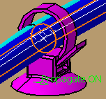
Propagate ON (green 3D label) identifies supports that can be re-arranged. Double-clicking the text toggles the label to Propagate OFF; the support will retain the previous arrangement.
-
Propagate OFF (red 3D label) identifies supports that cannot be re-arranged.
A contextual menu in the Propagate Arrangement list also lets you toggle the status from ON to OFF and vice-versa.
-
Optional: Click Propagate to keep the same segment arrangement in all selected supports in the route.
Click OK when done.