Double-click the Physical component node from the RFLP structure tree.
The workbench switches to Electrical Assembly Design.
Click Logical to Physical .
.
The
Logical to Physical Synchronization Manager dialog box appears.
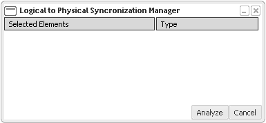
Select the logical or physical elements to be synchronized.
The selected elements are highlighted. In the Selected Elements list, all the selected elements are displayed with their type (either Logical or Physical).
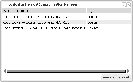
Note:
- You can remove the selected element by clicking it once again or right-click the element and select Remove.
- You can sort the elements by clicking the Selected Elements or Type list.
Click Analyze.
The selected elements are analyzed. An analysis progress bar helps to view the analysing status of elements and connections.

The dialog box appears as:
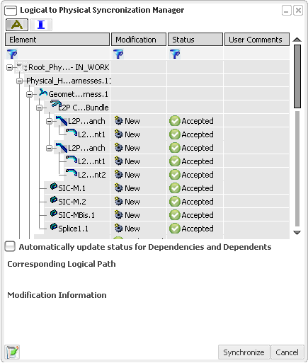
For more information about Modification and Status list, see More About Logical to Physical Synchronization.
You can generate an analysis report in the form of an HTML file in the synchronization report repository by clicking the Generate Report button. For more information about the HTML report, see About the HTML Report.
In the Status list, select Accepted or Rejected to determine either to synchronize the element or reject it.
If the rejected element has some dependencies, a warning message appears.

Click OK.
You can select the Automatically update status for Dependencies and Dependents check box to avoid the message.
Click
Synchronize to synchronize the selected elements.
The selected elements are synchronized.
You can generate synchronization report in the form of an HTML file in the synchronization report repository by clicking the Generate Report  button. For more information about the HTML report, see About the HTML Report.
In the 3D view, the predefined parts are instantiated from the database. The engineering connections are created between the physical components according to logical connections.
The electrical geometry is created and the branches are routed through the connectors and equipments. The branches will be created on certain criteria. The conductors are routed through branches.
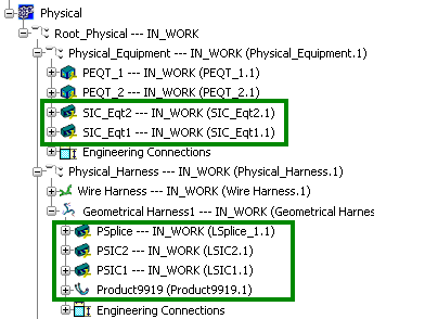
The components in the rectangular boxes in the above image are instantiated and created during the synchronization process.
Click Update All .
.
The physical components and electrical geometry are updated.
Select to check the connectivity of the electrical geometry.
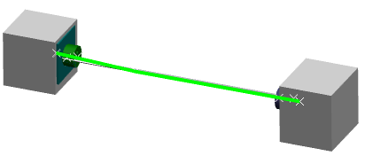
The electrical geometry highlighted in green color shows the connectivity of the electrical branch geometry.