About Electrical Branch Geometries | |||||
|
| ||||
Electrical Branch Geometries
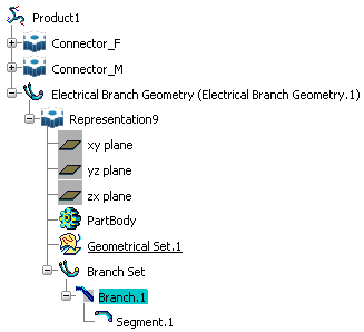
The electrical branch geometry represents the harness geometry and contains a set of branches. The electrical branch geometries are created in the Electrical Assembly Design workbench. At creation, an electrical branch geometry contains only one branch and one segment.

- Each branch can contain one or more segments that share the same center curve. The segment graphically represents the conductor envelope and has electrical properties. It is round by default.
- You can create segments having different profiles (round, elliptical and rectangular) as well as branches having multiple profiles that ensure more realistic harness designs.
- All branches in a electrical branch geometry are created under a Branch Set.
- Any construction geometry, for example route points, you explicitly create
is added under a Geometrical Set.
Note: You can delete a branch (and associated segment) but not a segment only.
- A dedicated option (Work with one electrical branch per electrical geometry) lets you choose whether the electrical geometry contains one or more electrical branch geometries.
![]()
Branch Creation and Edition
The branch can be created or edited depending on which workbench you are in.
The following table will help you understand whether you create or edit a branch depending on which workbench you are in and how far you have gone in your design.
| If you are in... | And... | Then the command... |
|---|---|---|
| Electrical Assembly Design > Electrical Branch Geometry | At least one electrical branch geometry exists with one branch, but no geometry has been associated and no route defined and, nothing is selected in the geometry area | Edits the branch |
| Electrical Part Design > Branch | At least one electrical branch geometry exists with one branch, but no geometry has been associated and no route defined and, nothing is selected in the geometry area | Edits the branch |
| Electrical Part Design > Branch | At least one electrical branch geometry exists with one branch fully defined (i.e. geometry associated and route defined) and, nothing is selected in the geometry area | Creates a new branch |
Diameter
When the branch contains only one segment, the diameter is managed at branch level (Diameter box in the Branch Definition dialog box).
When the branch contains more than one segment, diameter is managed at individual segment level in the Segments Definition dialog box or by double-clicking the segment in the specification tree. In this case, the Diameter box in the Branch Definition dialog box is unavailable.
Tight Turns
Specifying a bend radius at least equal to the diameter is recommended to avoid tight turns or self-intersecting geometry:

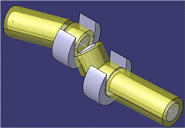
Self-intersecting geometry may result in not being able to visualize the turn in the geometry area:

A message informs you if the minimum bend radius of a segment is smaller than the diameter.